Design method of freely-adjustable angular airy beam mask plate

A technology of Airy beams and design methods, applied in optics, optical components, instruments, etc., to achieve the effect of important application prospects

Inactive Publication Date: 2018-10-19
HENAN UNIV OF SCI & TECH
View PDF7 Cites 3 Cited by
  • Summary
  • Abstract
  • Description
  • Claims
  • Application Information

AI Technical Summary

Problems solved by technology

Therefore, in summary, in the field of Airy beam research, there is still a lack of an angular Airy beam tha...

Method used


Image

  • Design method of freely-adjustable angular airy beam mask plate
  • Design method of freely-adjustable angular airy beam mask plate
  • Design method of freely-adjustable angular airy beam mask plate

Examples


Embodiment

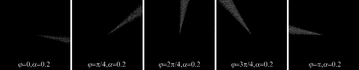
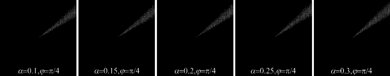
[0041] Taking a mask with a size of 512×512 as an example, an angular Airy beam mask with controllable spatial position of the main lobe and number of side lobes is given for a laser with a working wavelength of 532nm. The parameter v of the conical lens of the mask is 20, and the arbitrary angular ratio M is 0.2. The attenuation factor α is selected as 0.2, and the main lobe space position regulation factor The value is taken from 0 to π at an interval of π / 4, and finally a phase mask of an angular Airy beam whose spatial position of the main lobe can be adjusted is finally obtained according to the transmittance function of the mask in the specific embodiment. figure 1 That is, the different main lobe spatial position regulation factors used in the embodiment The phase mask of the angular Airy beam. Select the main lobe spatial position control factor is π / 4, the attenuation factor α is taken from 0.1 to 0.3 at an interval of 0.05, and finally obtains a phase mask of an...


PUM


Abstract

The invention relates to a design method of a freely-adjustable angular airy beam mask plate. The complex amplitude transmittance function t of the angular airy beam mask plate is obtained according to the complex amplitude of an angular airy beam, a conical lens factor and the phase of a blazed grating; and the phase of the complex amplitude transmittance function t of the mask plate is solved according to a calculation holographic principle, so that the freely-adjustable angular airy beam mask plate can be obtained. An angular airy beam of which the main lobe spatial position and side lobe number can be freely adjusted can be generated at the remote field of the mask plate; the spatial position of the main lobe of the angular airy beam and the number of the side lobes of the angular airybeam are controlled respectively by their respective parameters; and since the spatial position of the main lobe of the angular airy beam and the number of the side lobes of the angular airy beam canbe adjusted freely, the mask plate has a very bright application prospect in micromanipulation technology.

Description

technical field [0001] The invention relates to the field of particle light manipulation, in particular to a design method of an angular Airy beam mask plate with controllable main lobe spatial position and side lobe quantity. Background technique [0002] Airy beam transmission has the characteristics of non-diffraction, self-healing, and self-focusing. It has a wide range of applications in the fields of manipulating particles, generating photobullets, and synthesizing self-focusing beams. Therefore, it has become a very important research hotspot in the field of structured light fields in recent years. . [0003] In the field of quantum mechanics, Berry and Balazs made a very important prediction in 1979: the Schrödinger equation has a wave packet solution that follows the Airy function. But theoretical Airy beams have infinite energy, so they cannot be produced experimentally. In 2007, Siviloglou et al. found that the exponentially "truncated" Airy function is still a ...

Claims


Application Information

Patent Timeline
IPC IPC(8): G02B27/09G02B27/00
CPCG02B27/0012G02B27/0944
Inventor 李新忠张浩马海祥李贺贺唐苗苗台玉萍王静鸽
Owner HENAN UNIV OF SCI & TECH
Why Eureka
Try Eureka