Ultrasound suspending field visualized measurement method and its measuring systems

A technology of measurement system and measurement method, which is applied to measurement devices, measurement of ultrasonic/sonic/infrasonic waves, optics, etc., can solve problems such as low sensitivity, complicated measurement process, and non-adjustable measurement range, and achieve high precision, intuitive measurement results, The effect of simple and fast data processing

Inactive Publication Date: 2008-10-15
NORTHWESTERN POLYTECHNICAL UNIV
View PDF0 Cites 18 Cited by
  • Summary
  • Abstract
  • Description
  • Claims
  • Application Information

AI Technical Summary

Problems solved by technology

[0006] In order to avoid the deficiencies of the prior art, the present invention proposes a visual measurement method of the ultrasonic suspension field and its measurement system, which can

Method used


Image

  • Ultrasound suspending field visualized measurement method and its measuring systems
  • Ultrasound suspending field visualized measurement method and its measuring systems
  • Ultrasound suspending field visualized measurement method and its measuring systems

Examples


Embodiment 1

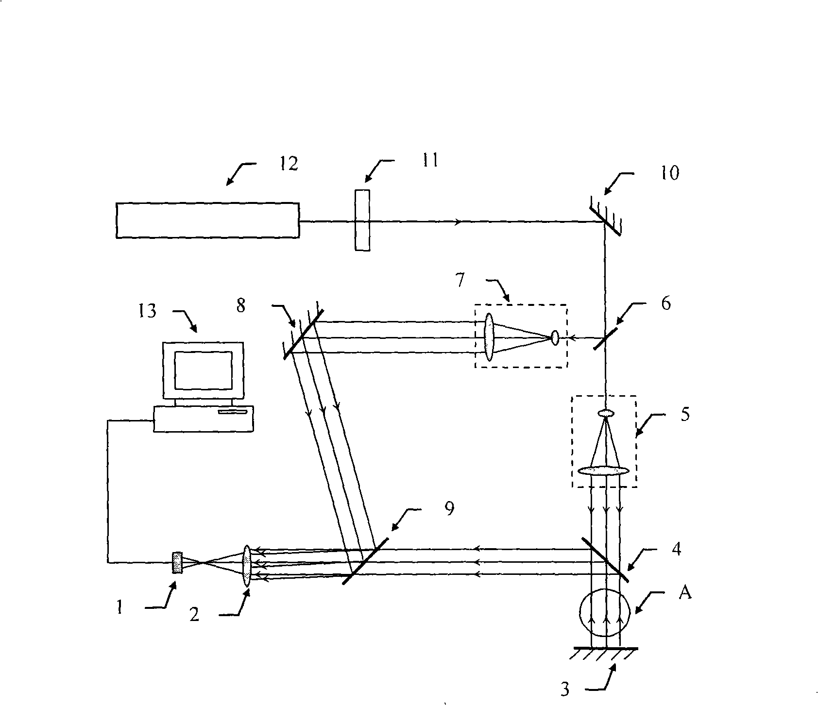
[0028] Embodiment 1: as figure 2 The shown measurement system includes a gas laser 12, an attenuator 11, a total reflection mirror 10, a beam splitter 6, a beam expander collimator 5, a half mirror 4, a total reflection mirror 3, a beam expander collimator 7, The total reflection mirror 8, the half mirror 9, the convex lens 2, the area array CCD1, and the ultrasonic field A to be measured contained therein.

[0029] The attenuator 11 is an adjustable optical attenuator, which is arranged on the optical path of the light beam emitted by the gas laser 12, and plays a role of attenuating the light intensity in order to prevent the image formed on the CCD from being too bright. The total reflection mirror 10 reflects the attenuated light to the beam splitter 6, and the beam splitter 6 is a beam splitter with an adjustable splitting ratio, and splits the beam into a first beam and a second beam. The first light beam is expanded and collimated by the beam expander and collimator 5...

Embodiment 2

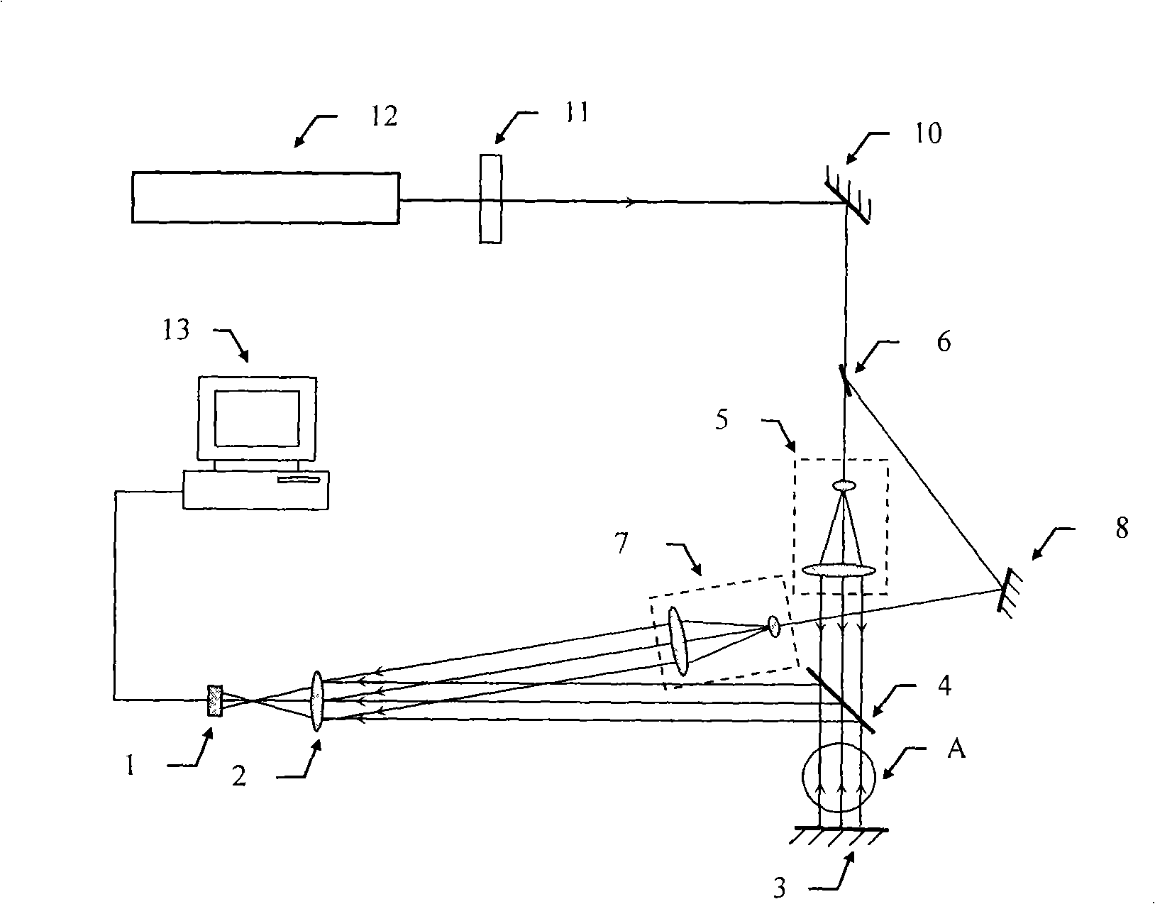
[0036] Example 2 as image 3 Shown: including gas laser 12, attenuator 11, total reflection mirror 10, beam splitter 6, beam expander collimator 5, half mirror 4, ultrasonic field to be measured A, total reflection mirror 3, beam expander collimator Straightener 7, total reflection mirror 8, convex lens 2 and area array CCD1.

[0037] In this embodiment, the half-mirror 9 is removed on the basis of the first embodiment, thereby simplifying the system. The main working process of the mode is basically the same as that of the first embodiment.

Embodiment 3

[0038] Example 3 as Figure 4 Shown: including semiconductor laser 16, attenuator 11, total reflection mirror 10, beam splitter 6, beam expander collimator 5, half mirror 4, ultrasonic field A to be measured, total reflection mirror 3, convex lens 14, Convex lens 15, beam expander collimator 7, total reflection mirror 8, half mirror 9, convex lens 2 and area array CCD1.

[0039] In this embodiment, on the basis of the first embodiment, an inverted telescope system consisting of a convex lens 14 and a convex lens 15 is added between the half mirror 4 and the half mirror 9 in the first optical path. The main working process is basically the same as that of the first embodiment, the difference is that in the main working process of the third embodiment, due to the addition of the inverted telescope system, the measurement system can adapt to the larger area of ​​the ultrasonic field to be measured , Beyond the acceptable range of CCD.

[0040] During the working process, when t...


PUM

PropertyMeasurementUnit
Wavelengthaaaaaaaaaa

Abstract

The invention relates to an ultrasound suspension field visible measuring method and a measuring system using the same. The technology is characterized in that: light beams emitted by a laser are divided into a first set of parallel beams and a second set of parallel beams; the first parallel beams run through an ultrasound suspension field to be measured, and are reflected and then run through the ultrasound suspension field to be measured along the original path, thereby forming measured object light; the second parallel beams are used as reference light, occur interference with the measured object light and form images on an area array CCD. The ultrasound suspension field visible measuring method has the advantages that: in the process of carrying out measurement, the method can avoid producing error, realize instantaneous record and detect the distribution of interference fringes caused by slight change of refractive index of the air due to sound field disturbance, so as to make a measuring result more intuitionistic and accurate. A digital hologram obtained by the measuring device CCD realizes various complex amplitude operations and manipulations in the real sense through digital reappearance so that a data process is simple, rapid and high precise. The measuring device can carry out real-time measurement to a large-size flow field and have great advantage for realizing undisturbed measurement of the ultrasound suspension field.

Description

technical field [0001] The invention relates to a method for visually measuring an ultrasonic levitation field and a measurement system thereof, which utilize digital holographic technology to realize the measurement of an ultrasonic levitation field. Background technique [0002] Acoustic levitation technology mainly uses the acoustic radiation force (Acoustic Radiation Force) or acoustic radiation pressure (Acoustic Radiation Pressure) generated by the high-intensity ultrasonic standing wave field, which can make common solids or liquids whose density is hundreds or even tens of thousands of times greater than air Overcoming the gravity of the earth and suspending in the air, it can also locate the air bubbles with a small density at a certain position in the liquid without floating to the liquid surface, which is an important means of container-free treatment. [0003] Since the ultrasonic suspension field is a standing wave field formed by sound waves in the air, it cann...

Claims


Application Information

Patent Timeline
IPC IPC(8): G01H9/00G02B27/10
Inventor 李恩普赵建林郑普超邸江磊
Owner NORTHWESTERN POLYTECHNICAL UNIV
Why Eureka
Try Eureka