
Incoherent laminated diffraction imaging system and imaging method achieving simultaneous multi-wavelength illumination

An imaging system and multi-wavelength technology, applied in the direction of scattering characteristic measurement, measurement device, and material analysis through optical means, can solve the problems of cumbersome operation, high coherence requirements, and long processing cycle

Active Publication Date: 2016-06-29
XI'AN INST OF OPTICS & FINE MECHANICS - CHINESE ACAD OF SCI
View PDF7 Cites 17 Cited by
  • Summary
  • Abstract
  • Description
  • Claims
  • Application Information

AI Technical Summary

Problems solved by technology

[0004] conventional lamination imaging technology Single-wavelength illumination is often used, even if multi-wavelength illumination is used to improve the restoration quality, sequential illumination is adopted, see (ActaPhys.Sin.Vol.65, No.1(2016)014204), the operation is cumbersome and the processing period is long; at the same time The coherence of light is highly required, and incoherent light illumination has always been considered unfavorable for diffraction imaging, see (DongSY, ShiradkarR, NandaP, ZhengGA2014Biomed.Opt.Express51757)

Method used


Image

  • Incoherent laminated diffraction imaging system and imaging method achieving simultaneous multi-wavelength illumination
  • Incoherent laminated diffraction imaging system and imaging method achieving simultaneous multi-wavelength illumination
  • Incoherent laminated diffraction imaging system and imaging method achieving simultaneous multi-wavelength illumination

Examples


specific Embodiment approach

[0124] In the process of verifying the imaging technology and the corresponding algorithm proposed by the present invention, we have further verified the present invention not only through experiments but also through simulation, because there is no error in the simulation, and the probe and spectral weights are given in the simulation process. Therefore, we only recover the true color pattern of the sample to be tested and the corresponding amplitude and phase information of the sample to be tested at each wavelength. The specific implementation of the simulation part is as follows:

[0125] The amplitude information of the true-color test sample used in the simulation is as follows: Figure 6a As shown, the phase information is as Figure 6b As shown, the complex amplitude distribution of the sample to be tested corresponding to the three wavelengths is as follows Figures 6c-6h shown, where Figure 6c , Figure 6e , Figure 6g The three wavelengths of red, green and bl...


PUM

PropertyMeasurementUnit
Diameteraaaaaaaaaa

Abstract

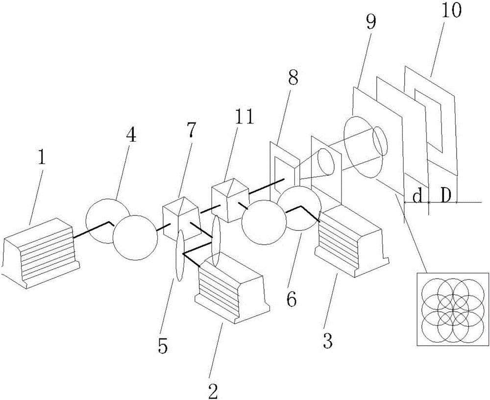
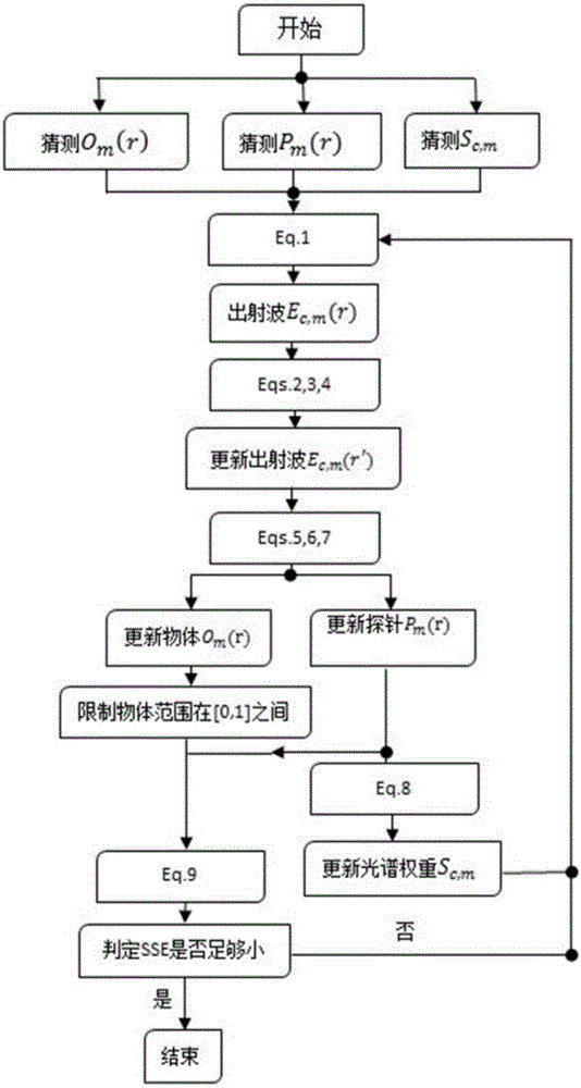
The invention provides an incoherent laminated diffraction imaging method achieving simultaneous multi-wavelength illumination.The imaging method comprises the following imaging processes that at least one kind of different lasers are adopted for illumination; emitted laser light is regulated to be horizontally emitted through double total reflection mirrors and then subjected to beam combination through double beam splitter prisms; the combined laser light is subjected to beam expansion through a spatial filter, collimated through an apochromatic lens and then reflected to probes; the probes perform laminated scanning on a sample to be measured; intensity information of diffraction images of the probe scanning positions is recorded through an imaging detector; the recorded diffraction image intensity information is substituted into a multiplexing iterative algorithm based on laminated scanning, and complex amplitude distribution of the sample to be measured, complex amplitude distribution of the probes and spectrum weights are recovered.According to the imaging scheme and the corresponding algorithm, not only can the complex amplitude sample to be measured corresponding to the different wave bands be recovered, but also the spectrum weights of the different wave bands and complex amplitude distribution of the illumination probes corresponding to the different wave bands can be recovered.

Description

technical field [0001] The invention belongs to the field of ptychography technology (Ptychography), in particular to an incoherent ptychography scheme for simultaneously illuminating a sample to be tested with multiple wavelengths, and proposes a multiplex ptychography algorithm. Background technique [0002] In fields such as biology and material science, traditional optical imaging techniques using lenses cannot meet today's increasing demand for high-resolution imaging. The resolution of these imaging technologies is mainly limited by the numerical aperture of the lens, especially in the X-ray field, it is extremely difficult to manufacture a lens with a large numerical aperture. Therefore, as a new lens-free imaging technology, stack imaging is attracting more and more attention. [0003] Laminated imaging technology is a lensless scanning coherent diffraction imaging technology. By controlling the illumination beam or the sample to be tested, different positions on th...

Claims


Application Information

Patent Timeline
IPC IPC(8): G01N21/47
CPCG01N21/4788
Inventor 韩洋何俊华闫亚东韦明智潘安万能
Owner XI'AN INST OF OPTICS & FINE MECHANICS - CHINESE ACAD OF SCI
Learn More