[0032] In order to make the objectives, technical solutions, and advantages of the present invention clearer, the embodiments of the present invention will be described in further detail below in conjunction with the accompanying drawings.
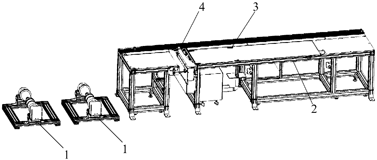
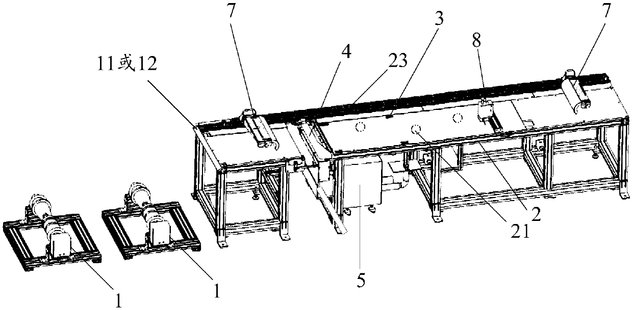
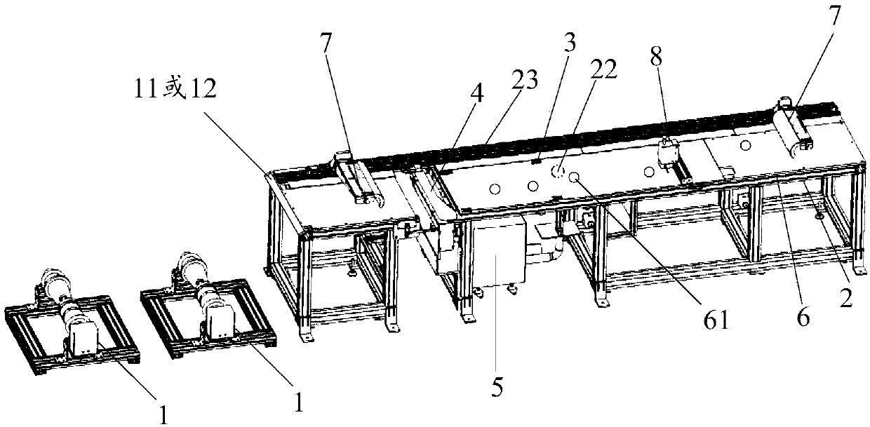
[0033] figure 1 It is a schematic structural diagram of a solar cell film material assembly equipment provided by an embodiment of the present invention. Such as figure 1 As shown, the solar cell film material assembly equipment includes: a film unwinding device 1, a laying platform 2, a film positioning and clamping device 3, and a film cutting device 4.
[0034] The film unwinding device 1 is used to load the card film and unwind the loaded film; the laying platform 2 is used to lay the film after the film unwinding device 1 unwinds; the film positioning and clamping device 3 and the laying platform 2 The connection is used to position and clamp the film laid on the laying platform 2; the film cutting device 4 is connected to the laying platform 2 and is used to cut the film laid on the laying platform 2.
[0035] It should be noted that the number of film unwinding devices 1 can be greater than or equal to 2, which can be two, three, four, etc., as long as the multilayer film can be installed on different film unwinding devices 1. It is sufficient to meet the requirements for making thin-film solar cells, and the multilayer film can be a water-blocking film, a sub-component, a back sheet and other films. The film unwinding device 1 can be arranged opposite to the laying platform 2 so that the film unwinded by the film unwinding device 1 can be linearly drawn to the laying platform 2 for laying, that is, the film can be linearly pulled after being pulled out from the film unwinding device 1 To the laying platform 2, there will be no wrinkles.
[0036] In addition, the table surface of the laying platform 2 is flat and smooth, and the laying platform 2 can be made of any material with a smooth and clean surface, as long as it does not damage or contaminate the film laid on the laying platform 2. The width of the table surface of the laying platform 2 can be equal to or greater than the width of the film, as long as the film can be smoothly laid on the laying platform 2. The laying platform 2 can be fixed on a bracket to increase the height of the laying platform 2 for easy operation.
[0037] Furthermore, the connection method of the film positioning and clamping device 3 and the laying platform 2 can be any of welding, snap connection, etc., and the film positioning and clamping device 3 can be connected to the laying platform 2 except for the film laying position. The outer position is connected to avoid damage to the film laid on the laying platform 2 at the connection between the film positioning and clamping device 3 and the laying platform 2. The number of film positioning and clamping devices 3 can be at least one, and the same film positioning and clamping device 3 can position and clamp the same length of multilayer film laid on the laying platform 2, and different film positioning and clamping devices 3 can Positioning and clamping the multilayer films of different lengths laid on the laying platform 2. The film positioning and clamping device 3 generally positions and clamps the first end of the film, and the position of the film positioning and clamping device 3 on the laying platform 2 can be determined according to the length of the film required to make the thin film solar cell.
[0038] Finally, the connection between the film cutting device 4 and the laying platform 2 can be any one of welding, snap connection, etc. The film cutting device 4 can be connected to the laying platform 2 at a position other than the film laying position. The connection between the film cutting device 4 and the laying platform 2 is prevented from causing damage to the film laid on the laying platform 2. The film cutting device 4 can be set on the laying platform 2 at a position closer to the film unwinding device 1, as long as the distance between the film cutting device 4 and the film positioning and clamping device 3 is equal to the length of the film required to make the thin film solar cell That's it.
[0039] In addition, the laying platform 2 can be provided with a first support rod and a second support rod. The film positioning and clamping device 3 can be movably connected with the first support rod and can be moved up and down through the first support rod. The film cutting device 4 can It is movably connected with the second support rod, and can be moved up and down by the second support rod, for example, the first support rod and the second support rod may both be telescopic rods.
[0040] When the thin-film solar cell is produced by the solar cell film material assembly equipment, for example, when the number of layers of the thin film required for the production of the thin-film solar cell is three, and the length of the first layer of film is the same as that of the second layer, When the length of the first film is different from the length of the third film, firstly, the laying platform 2 can be placed at a suitable position, and the three film unwinding devices 1 can be placed at positions opposite to the laying platform 2. Then set the film cutting device 4 on the laying platform 2 near the film unwinding device 1, and finally determine the position of a film positioning and clamping device 3 according to the length of the first film and the position of the film cutting device 4 as position A According to the length of the third layer of film and the position of the film cutting device 4, determine the position of the other film positioning and clamping device 3 as position B, and set the two film positioning and clamping devices 3 at the determined positions A and B respectively Place. Then, according to the laying order of the three layers of film, first unwind the first film loaded on the first film unwinding device 1, and pull the unwinded first film to the film at position A The positioning and clamping device 3 performs positioning and clamping, and the first film laid on the laying platform 2 is cut by the film cutting device 4. Then unwind the second film on the second film unwinding device 1 and pull the unrolled second film to the film positioning and clamping device 3 at position A for positioning and clamping. The second layer of film laid on the laying platform 2 is cut by the film cutting device 4. Then unwind the third film on the third film unwinding device 1 and pull the unrolled third film to the film positioning and clamping device 3 at position B for positioning and clamping. The third layer of film laid on the laying platform 2 is cut by the film cutting device 4. Finally, the cut three-layer thin film is processed to obtain a thin-film solar cell.
[0041] It is worth noting that since the solar cell film assembly equipment includes a film unwinding device 1, a laying platform 2, a film positioning and clamping device 3, and a film cutting device 4, it does not require workers to carry the film back and forth, and it can be used in sequence. The operations of unwinding, laying, positioning and clamping and cutting of the film are completed, which reduces the workload of workers and improves the production efficiency of thin-film solar cells. And since the film unwinding device 1 can load and unwind the film, the laying platform 2 can lay the film after the film unwinding device 1 unwinds, and the film positioning and clamping device 3 can adjust the film laid on the laying platform 2 For positioning and clamping, the film cutting device 4 can cut the film laid on the laying platform 2, so the process of unwinding, laying, positioning and clamping and cutting of the film is simple and convenient, easy to operate, and can reduce the burden on the film. Damage and pollution can further improve the performance of the thin-film solar cell produced.
[0042] Further, as figure 2 As shown, one end of the laying platform 2 close to the film unwinding device 1 may be provided with a rounded chamfer 11 or a cylindrical drum 12.
[0043] Among them, the rounded chamfer 11 and the cylindrical roller 12 can be made of any material with a smooth and clean surface, which not only saves the force required to pull the film after the film unwinding device 1 unwinds to the laying platform 2, but also It can avoid damaging and contaminating the film when the film after unwinding by the film unwinding device 1 is pulled onto the laying platform 2.
[0044] In the embodiment of the present invention, in order to make the film flatly laid on a plane, specifically, it can be realized by the following two structures:
[0045] The first structure: see figure 2 The solar cell membrane material assembly equipment may also include a vacuum power source 5, the laying platform 2 is provided with at least one suction hole 21 for absorbing the film; the vacuum power source 5 is connected to the at least one suction hole 21.
[0046] It should be noted that the at least one suction hole 21 on the laying platform 2 can be arranged at any position between the film positioning and clamping device 3 and the film cutting device 4 on the laying platform 2, and the at least one suction hole 21 can be multiple The small holes arranged in an array in rows and multiple columns may of course also be small holes arranged randomly, which is not limited in the embodiment of the present invention.
[0047] In addition, the vacuum power source 5 may be any one of a micro vacuum pump, a micro air pump, a micro air pump, and the like. The vacuum power source 5 can be connected to at least one suction hole 21 on the laying platform 2 through a hose. After the vacuum power source 5 is turned on, the air between the laying platform 2 and the film can be drawn through at least one suction hole 21 connected to the vacuum power source 5, so that the laying platform 2 and the film are in a vacuum state to adsorb the film on the laying On platform 2.
[0048] The second structure: see image 3 The solar cell membrane material assembly equipment may also include a vacuum suction table 6 and a vacuum power source 5. The vacuum suction table 6 is provided with at least one suction hole 61 for adsorbing the film, and the laying platform 2 is provided with a through hole 22; The platform 6 is attached to one side of the laying platform 2 and the vacuum power source 5 is connected to the through hole 22 on the other side of the laying platform 2.
[0049] It should be noted that the table surface of the vacuum suction table 6 is flat and smooth. The vacuum suction table 6 can be made of any material with a smooth and clean surface, as long as the film laid on the vacuum suction table 6 is not damaged or contaminated. The width of the table surface of the vacuum suction table 6 can be equal to or greater than the width of the film, as long as the film after unwinding by the film unwinding device 1 can be laid flat on the vacuum suction table 6. The structure of the suction hole 61 provided on the vacuum suction table 6 is similar to the structure of the suction hole 21 on the laying platform 2 in the above-mentioned first structure, and will not be repeated here.
[0050] In addition, the through hole 22 on the laying platform 2 can be arranged at any position between the film positioning and clamping device 3 and the film cutting device 4, and the vacuum power source 5 can be connected to the through hole on the other side of the laying platform 2 through a hose. The hole 22 is connected. After the vacuum power source 5 is turned on, the air between the vacuum suction table 6 and the film can be extracted through the through hole 22 connected to the vacuum power source 5 and the suction hole 61 on the vacuum suction table 6 to make The vacuum suction table 6 and the film are in a vacuum state to suck the film on the vacuum suction table 6.
[0051] It is worth noting that through the above-mentioned first structure and second structure, the film can be laid on the laying platform 2 or the vacuum suction table 6 smoothly. In this way, when the film to be laid is too long, no mechanical fixing is required. The film is fixed in a way to avoid damage to the film, save the process of mechanical installation and fixation, and improve the efficiency of fixing the film.
[0052] Further, as figure 2 with image 3 As shown, the solar cell film material assembly equipment may also include a welding device 7. The welding device 7 is connected to the laying platform 2 and is used for welding the film.
[0053] It should be noted that the number of welding devices 7 can be one, two, three, etc., as long as it can meet the needs of making thin-film solar cells. The welding device 7 can weld the film to other components, for example, can weld a bus bar to the film.
[0054] In addition, when the welding device 7 is connected to the laying platform 2, it can be connected to a fixed position on the laying platform 2; or, the laying platform 2 can be provided with a slide rail 23, and one end of the welding device 7 can be located in the slide rail 23. The welding device 7 can slide in the slide rail 23. In this way, when other components need to be welded to a predetermined position on the film, the welding device 7 can be slid to the predetermined position along the slide rail 23, and then the film is welded. The operation is simple, time-saving and labor-saving, thereby improving The efficiency of welding the film.
[0055] Further, as figure 2 with image 3 As shown, the solar cell film material assembly equipment may also include a punching device 8. The punching device 8 is connected to the laying platform 2 and is used for punching the film.
[0056] It should be noted that the number of the punching device 8 can be one, two, three, etc., as long as it can meet the needs of making thin-film solar cells. After the welding device 7 perforates a certain layer of film, the wire can pass through the hole of this layer of film to connect with other layers of film.
[0057] In addition, when the punching device 8 is connected to the laying platform 2, it can be connected to a fixed position on the laying platform 2. For example, the film positioning and clamping device 3 can be removed, and the punching device 8 can be connected to the film positioning and clamping device 3. Or, the laying platform 2 may be provided with a sliding rail 23, one end of the punching device 8 may be located in the sliding rail 23, and the punching device 8 can slide in the sliding rail 23. In this way, when a hole needs to be punched at a predetermined position on the film, the punching device 8 can be slid to the predetermined position along the slide rail 23 to perform the punching operation on the film. The operation is simple, time-saving and labor-saving, thereby improving The efficiency of perforating the film.
[0058] Further, the table surface of the laying platform 2 may be marked with scale lines. In this case, scale lines can be set only on any one of the two long sides of the laying platform 2. Of course, for more accurate readings, scales can also be set on both long sides of the laying platform 2. line.
[0059] In the specific implementation, the film cutting device 4 can be fixed on the laying platform 2 at a position close to the film unwinding device 1, and then according to the scale set on the laying platform 2, the length of the film to be laid and the film cutting device 4 To determine the position of the film positioning and clamping device 3. In the same way, the positions of the welding device 7 and the punching device 8 can also be determined according to the scale lines set on the laying platform 2.
[0060] It is worth noting that the setting of scale lines on the table of the laying platform 2 makes the position determination of the film positioning and clamping device 3, the welding device 7 and the punching device 8 more convenient and intuitive, and it does not require personnel to measure and take. The film positioning and clamping device 3, the welding device 7 and the punching device 8 are arranged at accurate positions, thereby saving the cost of manufacturing the thin film solar cell.
[0061] In the embodiment of the present invention, since the solar cell film material assembly equipment includes a film unwinding device 1, a laying platform 2, a film positioning and clamping device 3, and a film cutting device 4, there is no need for workers to carry the film back and forth. The unwinding, laying, positioning and clamping and cutting operations of the film are completed in sequence, which reduces the workload of workers and improves the production efficiency of thin-film solar cells. And since the film unwinding device 1 can load and unwind the film, the laying platform 2 can lay the film after the film unwinding device 1 unwinds, and the film positioning and clamping device 3 can adjust the film laid on the laying platform 2 For positioning and clamping, the film cutting device 4 can cut the film laid on the laying platform 2, so the process of unwinding, laying, positioning and clamping and cutting of the film is simple and convenient, easy to operate, and can reduce the burden on the film. Damage and pollution can further improve the performance of the thin-film solar cell produced.
[0062] The above descriptions are only preferred embodiments of the present invention and are not intended to limit the present invention. Any modification, equivalent replacement, improvement, etc. made within the spirit and principle of the present invention shall be included in the protection of the present invention. Within range.