Passive optical network link fault monitoring method based on optical coding and optical time-domain reflectometer

An optical time domain reflectometer and passive optical fiber network technology, which is applied in the optical fiber field, can solve the problems of unfavorable multi-branch link passive optical fiber network monitoring and maintenance, time-consuming and the like, and achieves a simple and easy method to solve the monitoring and maintenance problems. Line, low cost effect

Inactive Publication Date: 2018-10-19
SOUTHEAST UNIV
View PDF11 Cites 9 Cited by
  • Summary
  • Abstract
  • Description
  • Claims
  • Application Information

AI Technical Summary

Problems solved by technology

However, this method can only measure one link at a time, and N links need N measurements, which is time-consuming
At the same time, this method requires that N links must use N+1 detection optical pulse signals of different wavelengths, which is not conducive to the monitoring and maintenance of multi-branch link passive optical fiber networks

Method used


Image

  • Passive optical network link fault monitoring method based on optical coding and optical time-domain reflectometer
  • Passive optical network link fault monitoring method based on optical coding and optical time-domain reflectometer
  • Passive optical network link fault monitoring method based on optical coding and optical time-domain reflectometer

Examples


Embodiment Construction

[0023] The technical solutions of the present invention will be further described below in conjunction with the accompanying drawings and embodiments.

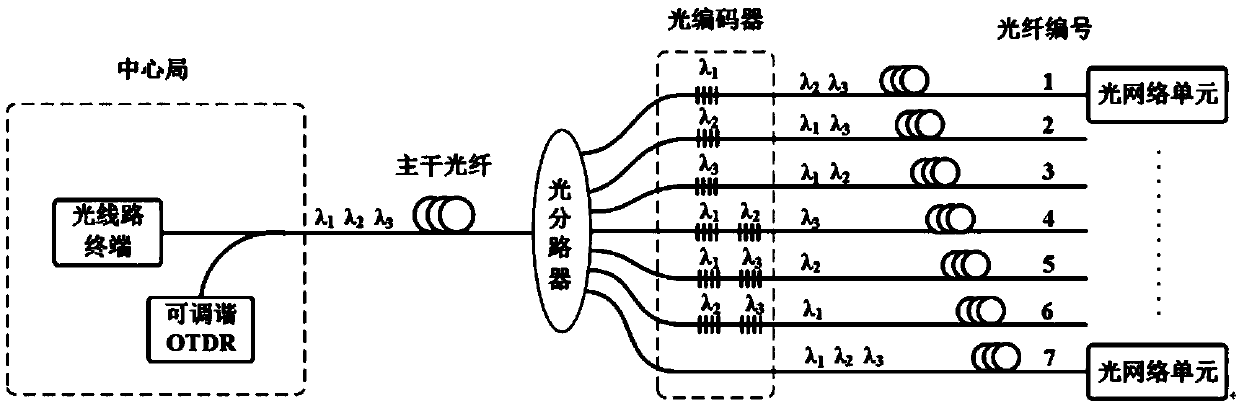
[0024] Such as Figure 1-2 As shown, the passive optical fiber network link fault monitoring method based on optical coding and optical time domain reflectometer described in the present invention adopts tunable optical time domain reflectometer and two-dimensional optical coding method at the same time, to the passive optical fiber network ( PON) link for fault location and fault identification. Tunable optical time domain reflectometers are located in the central office of passive optical fiber networks. The two-dimensional optical encoder is located on the remote passive optical splitter, or at the front end of the optical network unit (ONU), and is realized by fiber Bragg gratings with different reflection wavelengths.

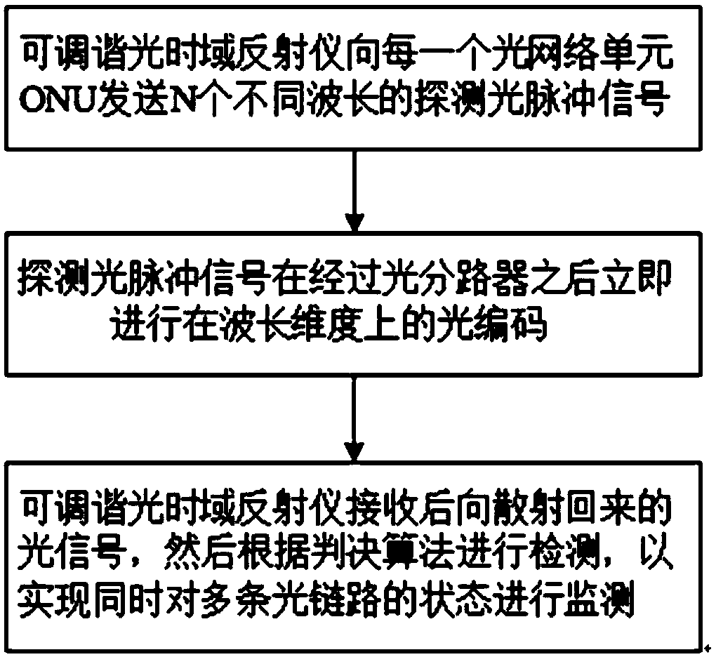
[0025] Such as figure 1 As shown, the flow process of the method of the present invention includes: ...


PUM


Abstract

The invention discloses a passive optical network link fault monitoring method based on optical coding and an optical time-domain reflectometer. A tunable optical time-domain reflectometer transmits detected optical pulse signals with different wavelengths to optical network units; two-dimensional optical coding is carried out on the detected optical pulse signals at a shunt unit at a remote-end node or an ONU front end; the tunable optical time-domain reflectometer receives a backscattered OTDR reflection spectrum in real time as a measurement spectrum; the tunable optical time-domain reflectometer receives a backscattered optical signal when each fiber link state is normal and OTDR reflection spectrum of different wavelengths are measured as reference spectrums; for the detected opticalpulses with different wavelengths, a minimum mean square error between the reference spectrum and the measurement spectrum is calculated as a decision parameter; and according to a decision detectionalgorithm, decision detection is carried out to realize simultaneous monitoring of states of multiple optical links. The decision detection algorithm is simple and practical; the optical fiber link fault monitoring is accurate; and the monitoring and maintenance costs of the optical link are effectively reduced.

Description

technical field [0001] The invention belongs to the field of optical fiber technology, and in particular relates to a passive optical fiber network link fault monitoring method based on optical coding and optical time domain reflectometer. Background technique [0002] The traditional optical fiber link inspection and maintenance method is difficult to troubleshoot and takes a long time to troubleshoot, which has a great impact on the normal operation of the optical network, affects the user experience, and also causes huge economic losses to network operators. Therefore, monitoring the health status of each optical link in real time and quickly locating fiber fault points are very important for optical networks. [0003] In order to solve the detection problem of PON links, many PON link monitoring methods have been proposed. Through searching the existing literature, it is found that in the record of Chinese patent CN103580749B, the optical fiber Bragg grating is used to ...

Claims


Application Information

Patent Timeline
Patent Type & Authority Applications(China)
IPC IPC(8): H04B10/071H04B10/077H04B10/079
CPCH04B10/071H04B10/0771H04B10/0791
Inventor 朱敏李贵鑫张圣羽孙卿
Owner SOUTHEAST UNIV
Why Eureka
Try Eureka