Pin bending device

A bending device and pin technology, applied in the field of electronic component manufacturing, can solve the problems of bending deviation and inconsistent bending degree of multiple pins, so as to solve the problem of large deviation of bending degree and ensure production Processing quality, beneficial to the effect of long-term use

Active Publication Date: 2018-10-23
泸州龙芯微科技有限公司
View PDF6 Cites 7 Cited by
  • Summary
  • Abstract
  • Description
  • Claims
  • Application Information

AI Technical Summary

Problems solved by technology

[0004] The present invention intends to provide a pin bending device to solve the problem that some pins of electronic component

Method used


Image

  • Pin bending device
  • Pin bending device

Examples


Embodiment Construction

[0020] The present invention will be described in further detail below by means of specific embodiments:

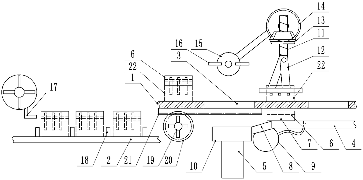
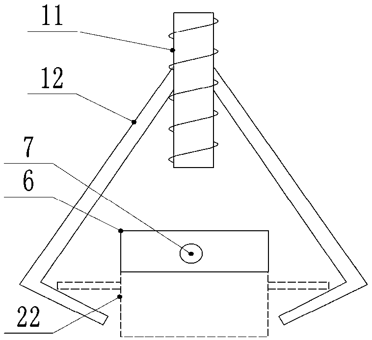
[0021] The reference signs in the drawings of the description include: feeding conveyor belt 1, discharging conveyor belt 2, perforation 3, conveying table 4, ejector rod 5, insert block 6, strip-shaped through hole 7, inclined plate 8, air bag 9, feeding table 10. Lead screw 11, bending rod 12, driving bevel gear 13, driven bevel gear 14, runner 15, lever 16, blowing pipe 17, baffle plate 18, fan wheel 19, spur gear 20, rack 21, Electronic components22.

[0022] Example figure 1 Shown: a pin bending device, including a feed conveyor belt 1, a discharge conveyor belt 2, a transmission mechanism, a bending mechanism, a toggle mechanism and a separation mechanism.

[0023] The feed conveyor belt 1 is driven by the feed roller, and the feed roller is connected with a motor and a bayonet pin. The discharge conveyor belt 2 is conveyed by the discharge roller, and the dischar...


PUM


Abstract

The invention relates to the field of manufacturing of electronic components, and discloses a pin bending device. The pin bending device comprises a feeding conveying belt provided with a metal blockand a plurality of through holes which are arranged at intervals. A bending mechanism is arranged above the feeding conveying belt. A conveying table and a slidable ejector rod are arranged below thefeeding conveying belt. A magnetic insertion block is slidably arranged on the conveying table and is located on the metal block. An oblique plate is hinged to the front end of the conveying table. The end, away from the conveying table, of the oblique plate is hinged to the ejector rod. An airbag which intermittently abuts against the oblique plate is arranged under the oblique plate and is connected with an air inlet pipe and an air outlet pipe. An air inlet one-way valve is arranged on the air inlet pipe. An air outlet one-way valve is arranged on the air outlet pipe. A feeding table is arranged on the ejector rod and right faces one through hole in the feeding conveying belt. A shifting mechanism right facing the ejector rod is arranged above the feeding conveying belt. By adoption ofthe pin bending device, the problem that certain pins of electronic components are excessively bent, the bending degrees of multiple pins are inconsistent, and consequentially, bending deviations arecaused is solved.

Description

technical field [0001] The invention relates to the field of production and manufacturing of electronic components, in particular to a pin bending device. Background technique [0002] Electronic components are components of electronic components and electric small machines and instruments. They are often composed of several parts and can be used in similar products. They often refer to certain parts in industries such as electrical appliances, radios, and instruments, such as capacitors and transistors. The general term for sub-devices such as hairsprings and springs, including resistors, capacitors, potentiometers, electronic tubes, radiators, electromechanical components, connectors, semiconductor discrete devices, electroacoustic devices, laser devices, electronic display devices, optoelectronic devices, sensors, etc. , common such as diodes. [0003] In the manufacturing process of electronic components, it is necessary to bend the pins. However, the existing pin bend...

Claims


Application Information

Patent Timeline
IPC IPC(8): B21F1/00B21F23/00
CPCB21F1/004B21F23/005
Inventor 黄晓波
Owner 泸州龙芯微科技有限公司
Why Eureka
Try Eureka