X-shaped guide rail of first-level transmission high-speed precise warm die forging machine

A die forging machine and guide rail technology, applied in the field of X-shaped guide rails, can solve problems such as affecting product accuracy, forging errors, clamping brakes, etc., to achieve uniform distribution of gaps, reduction of matching parts, and improved guidance.

Pending Publication Date: 2018-10-23
浙江精勇精锻机械有限公司
View PDF0 Cites 2 Cited by
  • Summary
  • Abstract
  • Description
  • Claims
  • Application Information

AI Technical Summary

Problems solved by technology

[0003] (1) The slider continues to be heated during operation and thus expands, making the gap between the guide rails uneven and affecting the accuracy of the product
[0004] (2) After thermal expansion, the gap between the guide rails becomes smaller, which may cause clamping, resulting in problems such as insufficient brakes or mold jamming.
[0005] (3) If it is necessary to adjust the gap accuracy of the slider in the future, it will be inconvenient
[0006] (4) The gap accuracy adjustment range of the slider is small, which is easily limited by the product
[0007] In addition, the dynamic unbalance state of the slider in motion or the error of manufacturing and human adjustment will cause the actuating position of the slider to deviate from the theoretical design value.
If the instantaneous lateral displacement generated when the slider is subjected to an eccentric load is compared with that during the rotation, the current box-type guide rails will cause the slider guide rails to be damaged due to the instantaneous displacement due to the uneven and stable gap between the guide rails and the large error gap. Excessive anti-balance and eccentric load force with the left and right guide plates on the frame will cause excessive errors in the produced forgings and affect the quality

Method used


Image

  • X-shaped guide rail of first-level transmission high-speed precise warm die forging machine
  • X-shaped guide rail of first-level transmission high-speed precise warm die forging machine
  • X-shaped guide rail of first-level transmission high-speed precise warm die forging machine

Examples


Embodiment Construction

[0034] In order to make the purpose, technical solutions and advantages of the present application clearer, the technical solutions in the embodiments will be clearly and completely described below in conjunction with the accompanying drawings in the embodiments,

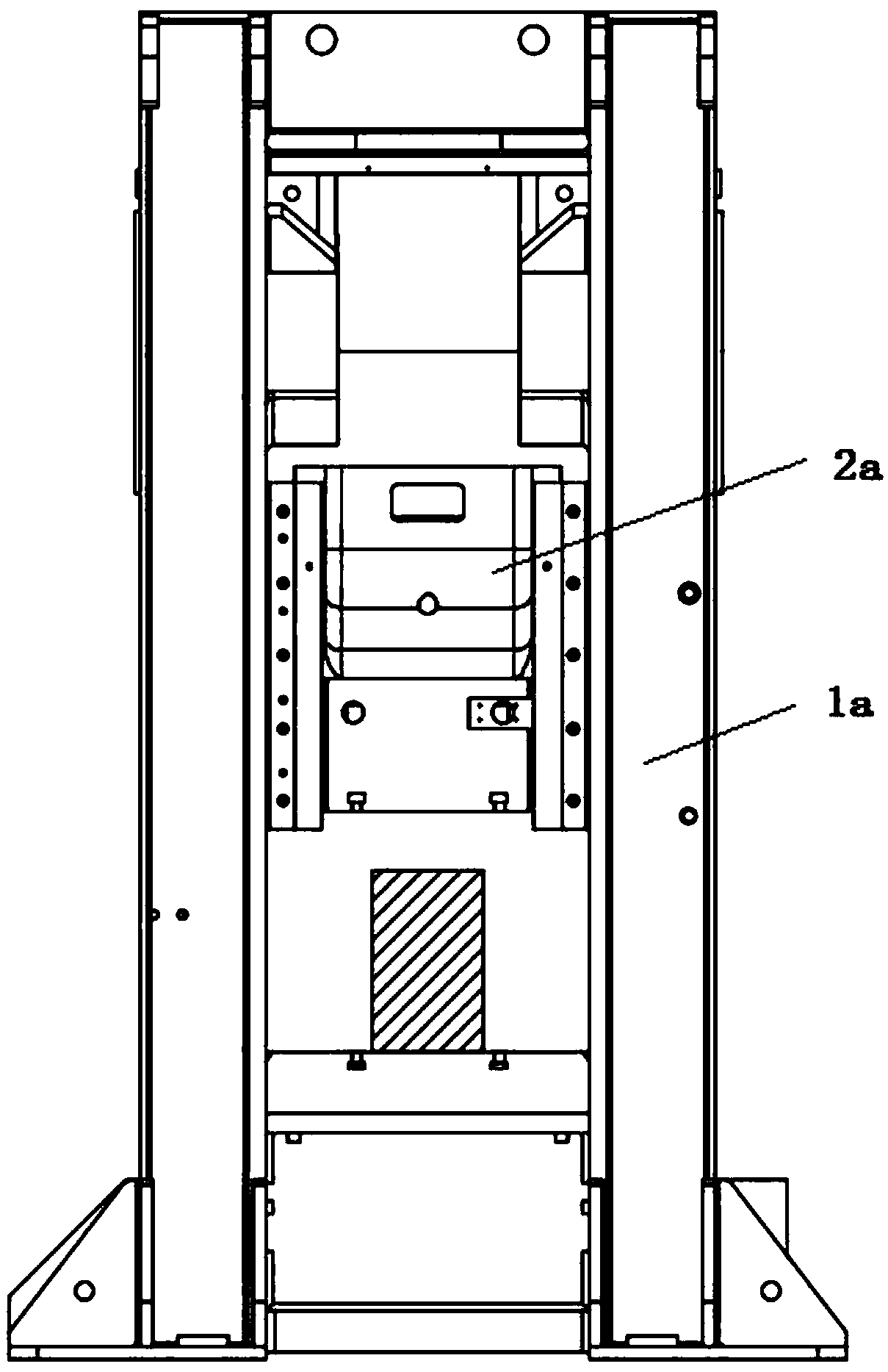
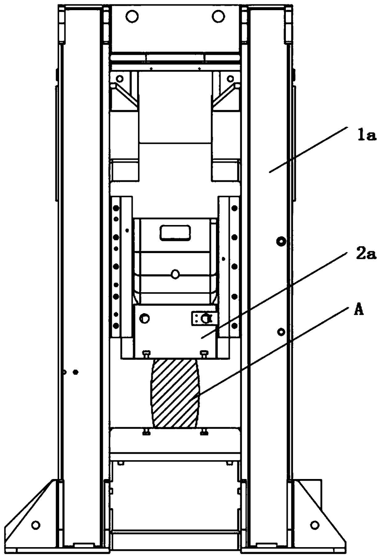
[0035] See Figure 1-2 , the slider guide rail structure in the prior art is a box-type fit, the slider 2a is driven by power components such as an eccentric shaft, a connecting rod, and a motor to move on the frame 1a, and forges the workpiece A;

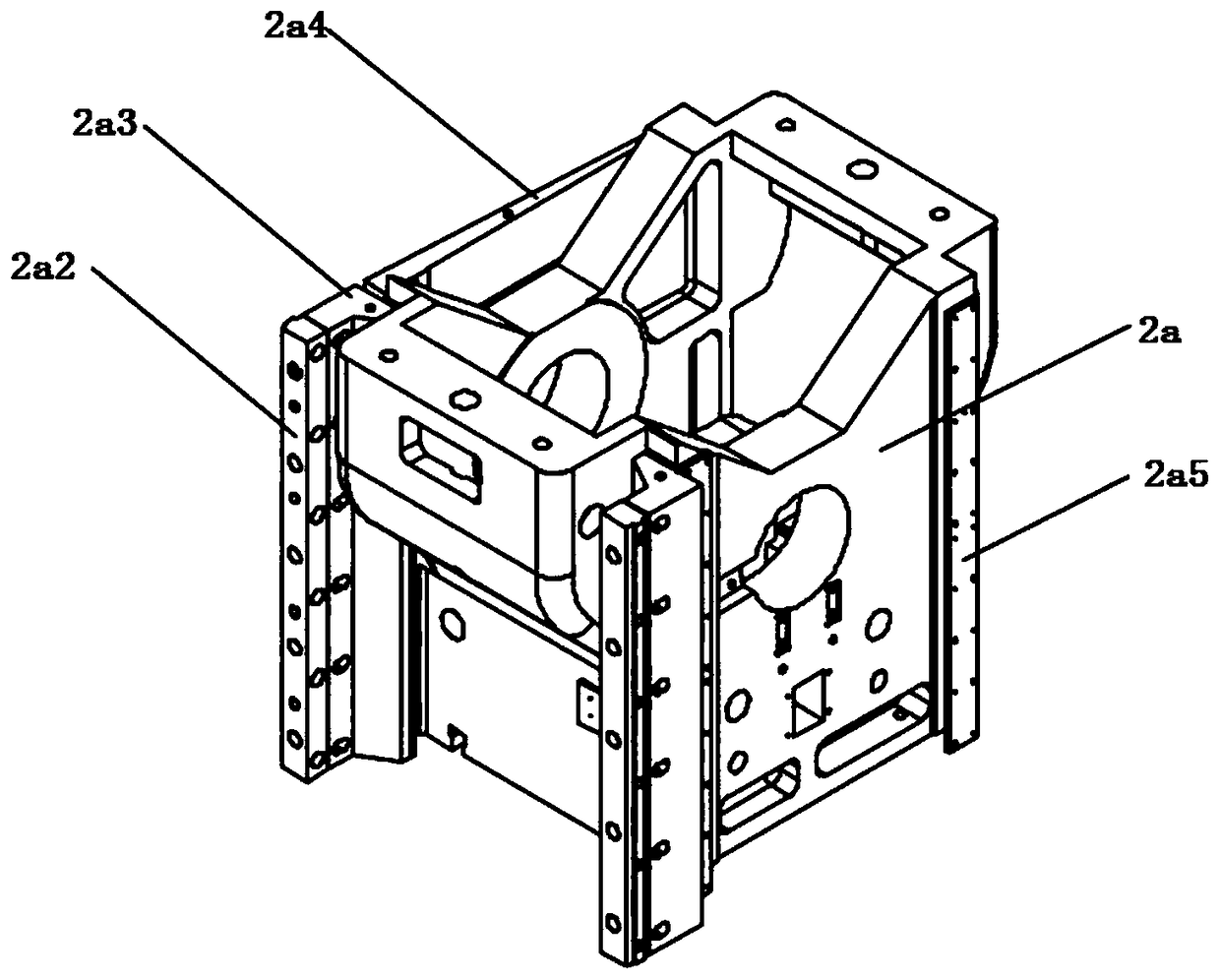
[0036] See Figure 3-4 , the four corners of the slider 2a have a guide plate 2a3 and two mutually perpendicular guide copper plates 2a5, a total of eight pieces, which are adjusted by the guide plate adjustment period 2a2, and the slider 2a also has a wedge-shaped guide plate 2a4.

[0037] The slider 2a with this structure is continuously heated during operation and thus expands, making the gap between the guide rails uneven and affecting the accuracy of the product; a...


PUM


Abstract

The invention discloses an X-shaped guide rail of a high-speed precise warm die forging machine. The X-shaped guide rail comprises a rack, a sliding block and a sliding block guide rail structure. Thesliding block guide rail structure comprises a path guiding plate component. The path guiding plate component comprises four path guiding plates which are fixed to the rack and extend in the slidingdirection of the sliding block. Each path guiding plate is provided with a sliding slope inclining towards the outer side, and the extension line of each sliding slope can penetrate into the sliding block. The path guiding plates are symmetrically arranged on the two sides of the sliding block. The sliding slopes are arranged in a quadrangle manner, and the two diagonal sliding slopes are parallelto each other. The side wall of the sliding block is provided with sliding block guide rail slopes which correspond to the sliding slopes and are in sliding contact with the sliding slopes. The gapsbetween sliding block guide rails are distributed evenly, and the guide rail guiding precision and stability can be effectively improved; and after the sliding block is continuously heated during workand thermal expansion is generated, the precision of the guide rail gaps cannot be influenced, and accordingly the product quality is ensured.

Description

technical field [0001] The invention belongs to the technical field of guide rails for high-speed precision warm die forging machines, and in particular relates to an X-shaped guide rail for a high-speed precision warm die forging machine with primary transmission. Background technique [0002] The slider guide rail structure of the forging machine is the main part that can guide the slider and balance the eccentric load generated during forging when the slider reciprocates up and down in the frame. It is also the place to control and maintain the precision of the product. The slider moves status as figure 1 shown. However, the current slider guide rail structure is a box-type fit. There are two guide copper plates perpendicular to each other at the four corners of the slider, a total of eight pieces. The current slider guide rail structure is as follows: figure 2 As shown, its disadvantages are as follows: [0003] (1) The slider is continuously heated during operation ...

Claims


Application Information

Patent Timeline
Patent Type & Authority Applications(China)
IPC IPC(8): B21J13/04
CPCB21J13/04
Inventor 陈炯亨林东民陈俞廷
Owner 浙江精勇精锻机械有限公司
Why Eureka
Try Eureka