
Intelligent clamping joint assembly line

An assembly line and smart card technology, applied in metal processing, metal processing equipment, manufacturing tools, etc., can solve the problems of high labor intensity, low work efficiency, and difficulty in mastering the stroke of operators.

Active Publication Date: 2018-10-23
新昌县玮康电子科技有限公司
View PDF5 Cites 2 Cited by
  • Summary
  • Abstract
  • Description
  • Claims
  • Application Information

AI Technical Summary

Problems solved by technology

However, the work efficiency of this way of completing the assembly is too low, and the assembly cannot be completed quickly; moreover, the labor intensity of the operator is high, and it is not easy to grasp the stroke of the two workpieces during the assembly process, especially when the two workpieces are required to be relatively firm. The relatively tight assembly cannot meet the requirements in terms of assembly accuracy

Method used


Image

  • Intelligent clamping joint assembly line
  • Intelligent clamping joint assembly line
  • Intelligent clamping joint assembly line

Examples


Embodiment Construction

[0020] The present invention will be further described below in conjunction with the accompanying drawings and specific embodiments.

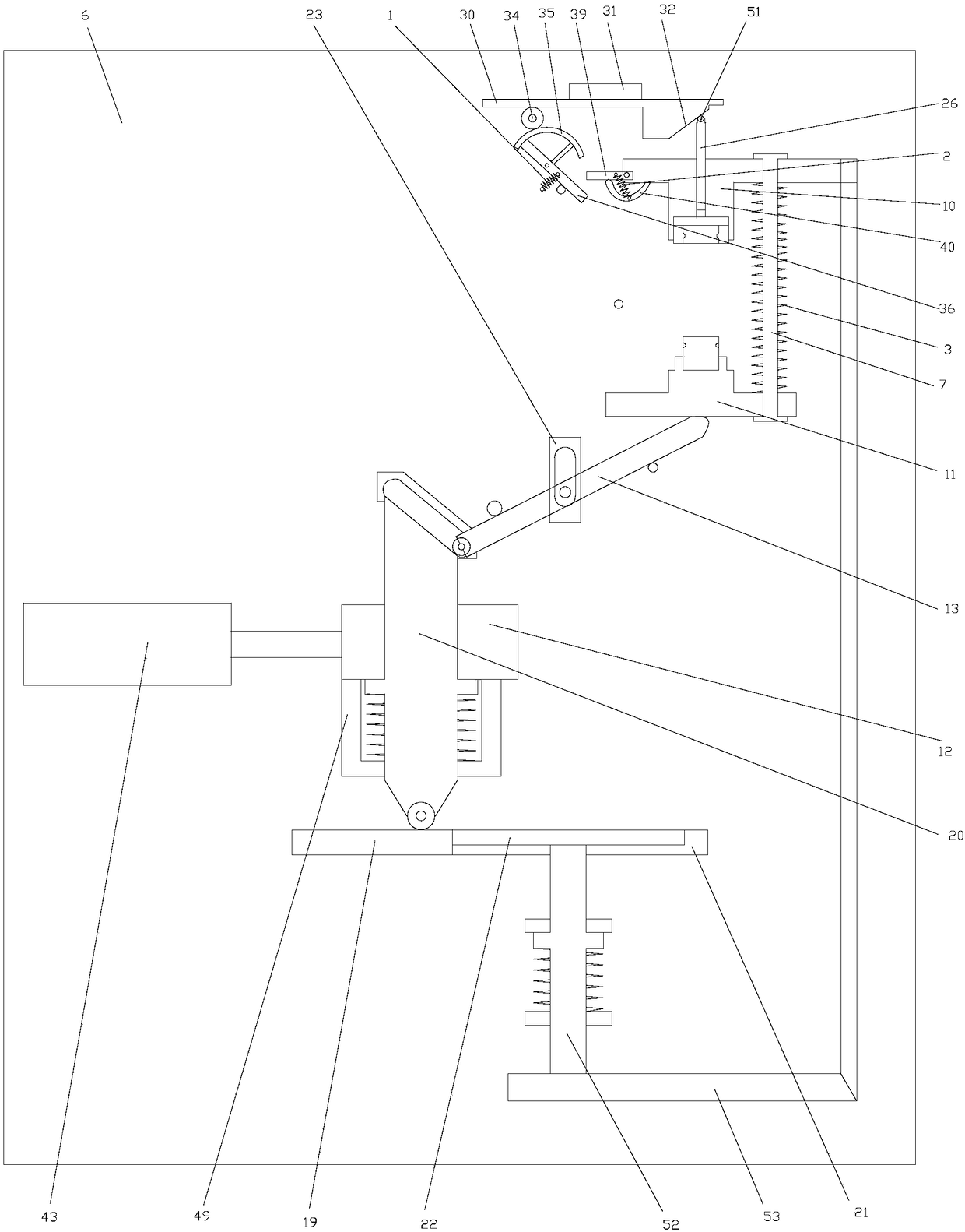
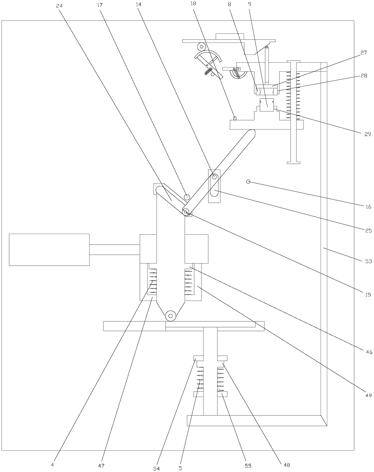
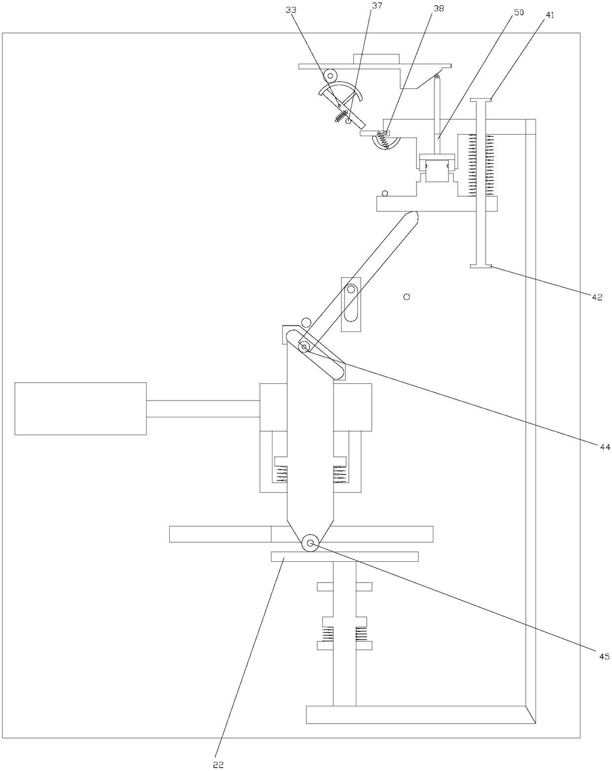
[0021]As shown in the figure, the assembly line of the smart snap connector of the present invention includes a base 6 on which a guide rod 7 is provided, and the guide rod 7 is sequentially sleeved with an upper sliding table 10 for accommodating the first workpiece 8 from top to bottom. With the sliding table 11 for accommodating the second workpiece 9, the sliding direction of the upper sliding table 10 and the sliding table 11 is opposite. The upper sliding table 10 mentioned here is opposite to the moving direction of the sliding table 11. When the sliding table 11 is closed, the two move closer to the middle position of the guide rod 7, and when the upper sliding table 10 and the sliding table 11 are parted, the two spread toward the two ends of the guide rod 7; the upper sliding table 10 and the sliding table 11 pass through elastic limit...


PUM


Abstract

The invention discloses an intelligent clamping joint assembly line. The intelligent clamping joint assembly line comprises a base. An upper sliding table and a lower sliding table are slidably connected to the base, the upper sliding table and the lower sliding table can be successively subjected to die closing and die splitting under the drive of a pushing block, and a discharging rod can perform automatic discharging on workpieces assembled in the upper sliding table during the die splitting process. In the processes of die closing, die splitting and discharging, the transmission reliability of the upper sliding table and the lower sliding table is high; and a vertical sliding column on the pushing block is matched with a swinging rod and a sliding plate to realize linkage of the uppersliding table and the lower sliding table, and thus the automation level of the entire device is increased. The intelligent clamping joint assembly line has higher assembly efficiency and higher assembly accuracy.

Description

technical field [0001] The invention relates to the field of automatic assembly, in particular to an assembly line for smart card connectors. Background technique [0002] In the field of mechanical parts assembly, it is often encountered in the workplace where two parts are snapped together. The specific occasion refers to that the outer wall of the first workpiece is provided with a groove, the second workpiece is a ring structure, and the inner wall of the second workpiece of the ring structure is provided with a convex line, the second workpiece needs to be sleeved on the first workpiece, and the second workpiece The convex strips on the second workpiece are engaged with the grooves on the first workpiece; or, the outer wall of the first workpiece is provided with convex strips, and the inner wall of the second workpiece of the ring structure is provided with grooves, and the second workpiece needs to be socketed on the second workpiece. On a workpiece, so that the two ...

Claims


Application Information

Patent Timeline
IPC IPC(8): B23P19/04
CPCB23P19/001B23P19/04
Inventor 丁天一
Owner 新昌县玮康电子科技有限公司
Learn More