Position and angle adjusting locating mechanism for drilling machine space of digging windlass and digging windlass

A technology of spatial position and angle adjustment, applied in drilling equipment, earthwork drilling, support devices, etc., can solve the problems of affecting work efficiency, poor swing effect of drilling rig, small swing radius, etc., and achieve the effect of high work efficiency

Inactive Publication Date: 2018-10-23
SANY HEAVY EQUIP
View PDF4 Cites 3 Cited by
  • Summary
  • Abstract
  • Description
  • Claims
  • Application Information

AI Technical Summary

Problems solved by technology

[0005] When protecting the side bolts, especially when the difference between the height of the bolt and the swing center of the drilling rig is small, the swing radius is very small, and the swing effect of the drilling rig is very poor, which affects the work efficiency

Method used


Image

  • Position and angle adjusting locating mechanism for drilling machine space of digging windlass and digging windlass
  • Position and angle adjusting locating mechanism for drilling machine space of digging windlass and digging windlass

Examples


Embodiment 1

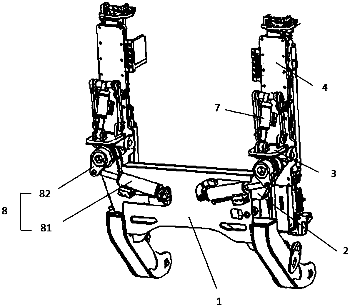
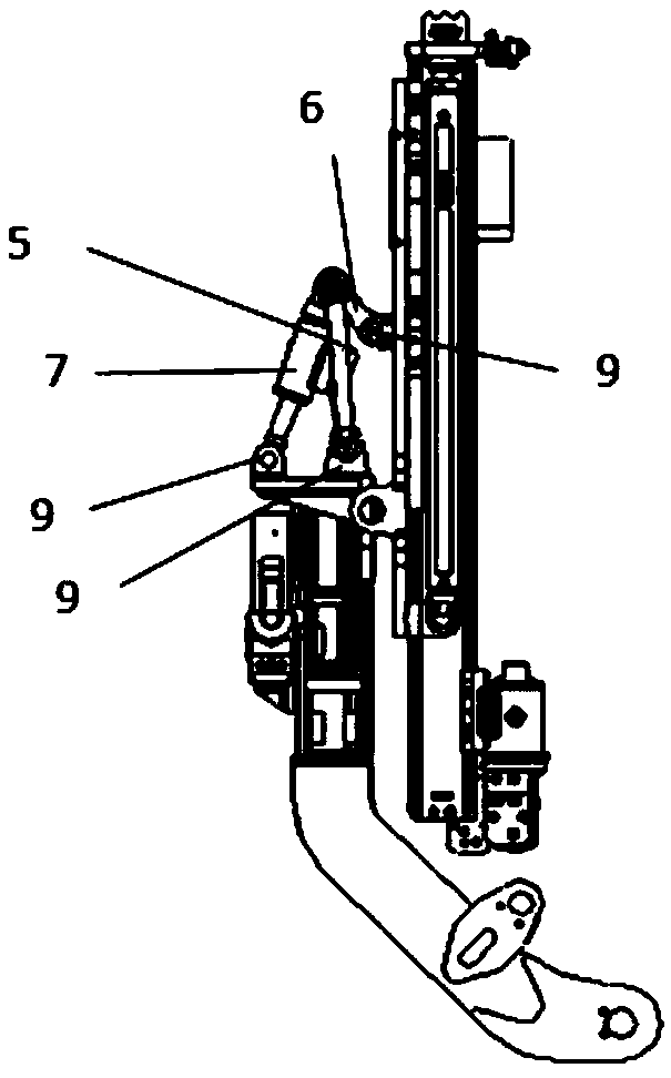
[0029] figure 1 It is a structural schematic diagram of the first viewing angle of the space position angle adjustment and positioning mechanism of the bolter drilling rig provided by Embodiment 1 of the present invention; figure 2 It is a structural schematic diagram of the second viewing angle of the space position angle adjustment and positioning mechanism of the bolter drilling rig provided by Embodiment 1 of the present invention; Figure 1-Figure 2 As shown, the bolter drilling rig spatial position angle adjustment and positioning mechanism provided by Embodiment 1 of the present invention includes a frame body 1, a telescopic beam 2, a turret 3, a drilling rig 4, a long swing rod 5, a short swing rod 6, and a swing drive device 7 and rotating device 8;

[0030] The telescopic beam 2 is installed in the frame body 1 and can move laterally in the frame body 1, the turret 3 is hinged on the telescopic beam 2, and the drilling machine 4 is installed on the turret 3 Above...

Embodiment 2

[0034] The space position and angle adjustment and positioning mechanism of the bolter drilling rig provided in the second embodiment is a further improvement on the space position and angle adjustment and positioning mechanism of the bolter drilling machine provided in the first embodiment. Figure 1-Figure 2 On the basis of the above, the space position angle adjustment and positioning mechanism of the bolter drilling rig provided in the second embodiment includes a frame body 1, a telescopic beam 2, a turret 3, a drilling rig 4, a long swing rod 5, a short swing rod 6, and a swing drive device 7 and rotating device 8;

[0035] The telescopic beam 2 is installed in the frame body 1 and can move laterally in the frame body 1, the turret 3 is hinged on the telescopic beam 2, and the drilling machine 4 is installed on the turret 3 Above, the long swing rod 5, the short swing rod 6, the drilling rig 4 and the turret 3 are hinged to each other to form a four-bar mechanism, one en...

Embodiment 3

[0042] The space position and angle adjustment and positioning mechanism of the bolter drilling rig provided in the third part of this embodiment is a further improvement on the space position and angle adjustment and positioning mechanism of the bolter drilling machine provided in the first embodiment. Figure 1-Figure 2 On the basis of the above, the space position and angle adjustment and positioning mechanism of the bolter drilling rig provided in the third embodiment includes a frame body 1, a telescopic beam 2, a turret 3, a drilling rig 4, a long swing rod 5, a short swing rod 6, and a swing drive device 7 and rotating device 8;

[0043]The telescopic beam 2 is installed in the frame body 1 and can move laterally in the frame body 1, the turret 3 is hinged on the telescopic beam 2, and the drilling machine 4 is installed on the turret 3 Above, the long swing rod 5, the short swing rod 6, the drilling rig 4 and the turret 3 are hinged to each other to form a four-bar mec...


PUM


Abstract

The invention discloses a position and angle adjusting locating mechanism for drilling machine space of a digging windlass. The mechanism comprises a frame body, a telescopic beam, a rotating frame, adrilling machine, a long oscillating rod, a short oscillating rod, an oscillating driving device and a rotating device; the telescopic beam is installed in the frame body and can move transversely inthe frame body, the rotating frame is hinged to the telescopic beam, and the drilling machine is installed on the rotating frame; the long oscillating rod, the short oscillating rod, the drilling machine and the rotating frame are mutually hinged to form a four-rod mechanism, and one end of the oscillating driving device is hinged to one hinged point of the four-rod mechanism; the other end of the oscillating driving device is hinged to the rotating frame, one end of the rotating device is in rigid connection with the rotating frame, and the other end of the rotating device is hinged to the telescopic beam. When an anchor rod is hit at any position in a roadway, the oscillating radius of the drilling machine is not changed, the oscillating range cannot be changed because of different rotating positions of the drilling machine, the four-rod mechanism can extend the oscillating range of the drilling machine, and the oscillating driving device utilizes the smaller route to drive the drilling machine to oscillate in a larger range. Based on the position and angle adjusting locating mechanism, the invention further provides the digging windlass.

Description

technical field [0001] The invention relates to a positioning mechanism, in particular to a positioning mechanism for adjusting the space position angle of a bolter drilling rig and a bolter. Background technique [0002] When a bolter digger is used for bolt digging operations in coal mines, the stop position of the bolter digger will not be strictly on the center of the roadway, and sometimes even deviates greatly. [0003] The anchor rods of the top plate and the side will not be strictly on the same line, which requires the drilling rig of the bolter miner to be able to adjust the spatial position and angle. [0004] There are certain defects in the space position angle adjustment positioning mechanism of many existing bolter drilling rigs, and the reason is that the sequence of the rotation and swing actions of the drilling rigs is improperly arranged. [0005] When protecting the side bolt, especially when the difference between the height of the bolt and the height o...

Claims


Application Information

Patent Timeline
Patent Type & Authority Applications(China)
IPC IPC(8): E21B15/04E21D20/00
CPCE21B15/04E21D20/003
Inventor 刘林林刘锋赵成雷高富强
Owner SANY HEAVY EQUIP
Why Eureka
Try Eureka