Chassis dynamometer test bench driven by permanent magnet synchronous motor

A permanent magnet synchronous motor and chassis dynamometer technology, which is used in the testing of machine/structural components, vehicle testing, measuring devices, etc., can solve the problems that each wheel cannot be accurately tested, the mechanism is complex, etc., to achieve convenient installation, The effect of reducing the difficulty of processing

Pending Publication Date: 2018-10-23
HUBEI HUANYEE ELECTROMAGNETIC EQUIP ENG TECH CO LTD
View PDF10 Cites 7 Cited by
  • Summary
  • Abstract
  • Description
  • Claims
  • Application Information

AI Technical Summary

Problems solved by technology

This technical solution can guide the chassis dynamometer, and can also guide the wheelbase vehicle to perform the chassis dynamometer. It is mainly aimed at vehicles with multiple axles, but it cannot accurately test each wheel of the full-time four-wheel drive, and the mechanism is complicated.

Method used


Image

  • Chassis dynamometer test bench driven by permanent magnet synchronous motor
  • Chassis dynamometer test bench driven by permanent magnet synchronous motor
  • Chassis dynamometer test bench driven by permanent magnet synchronous motor

Examples


Embodiment 1

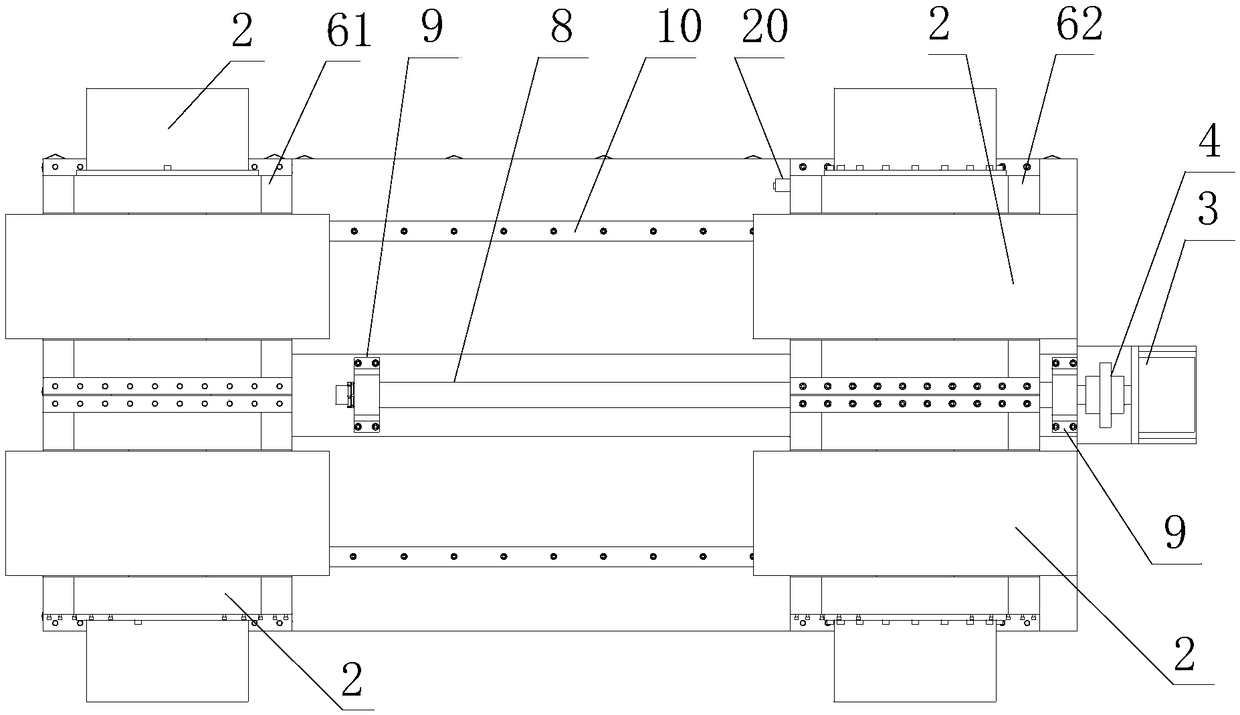
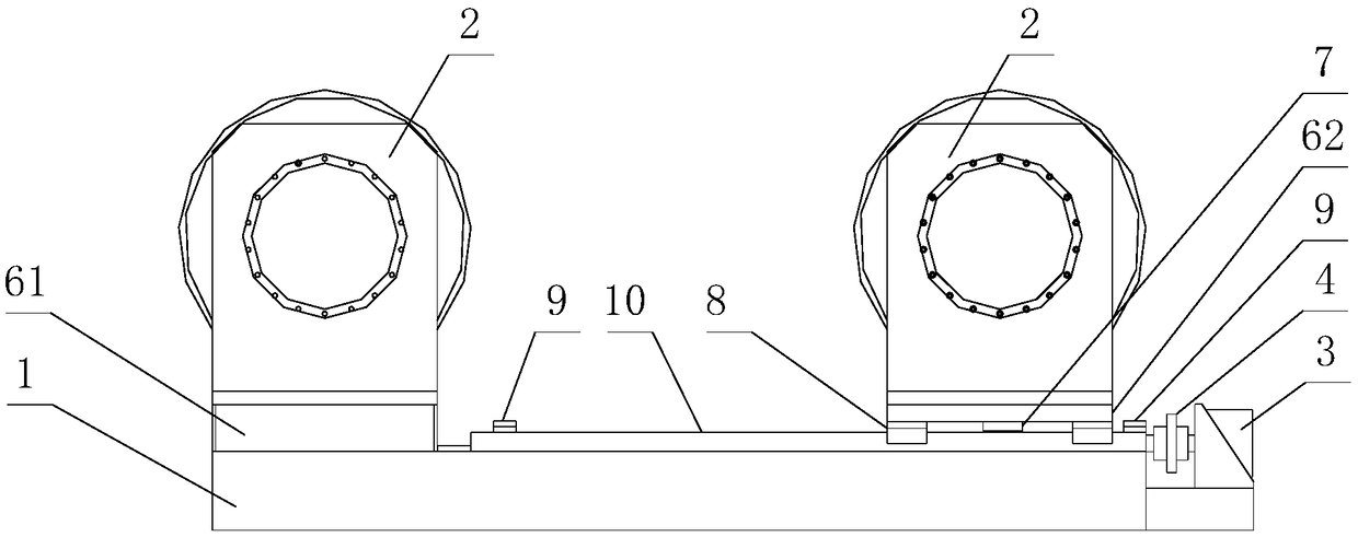
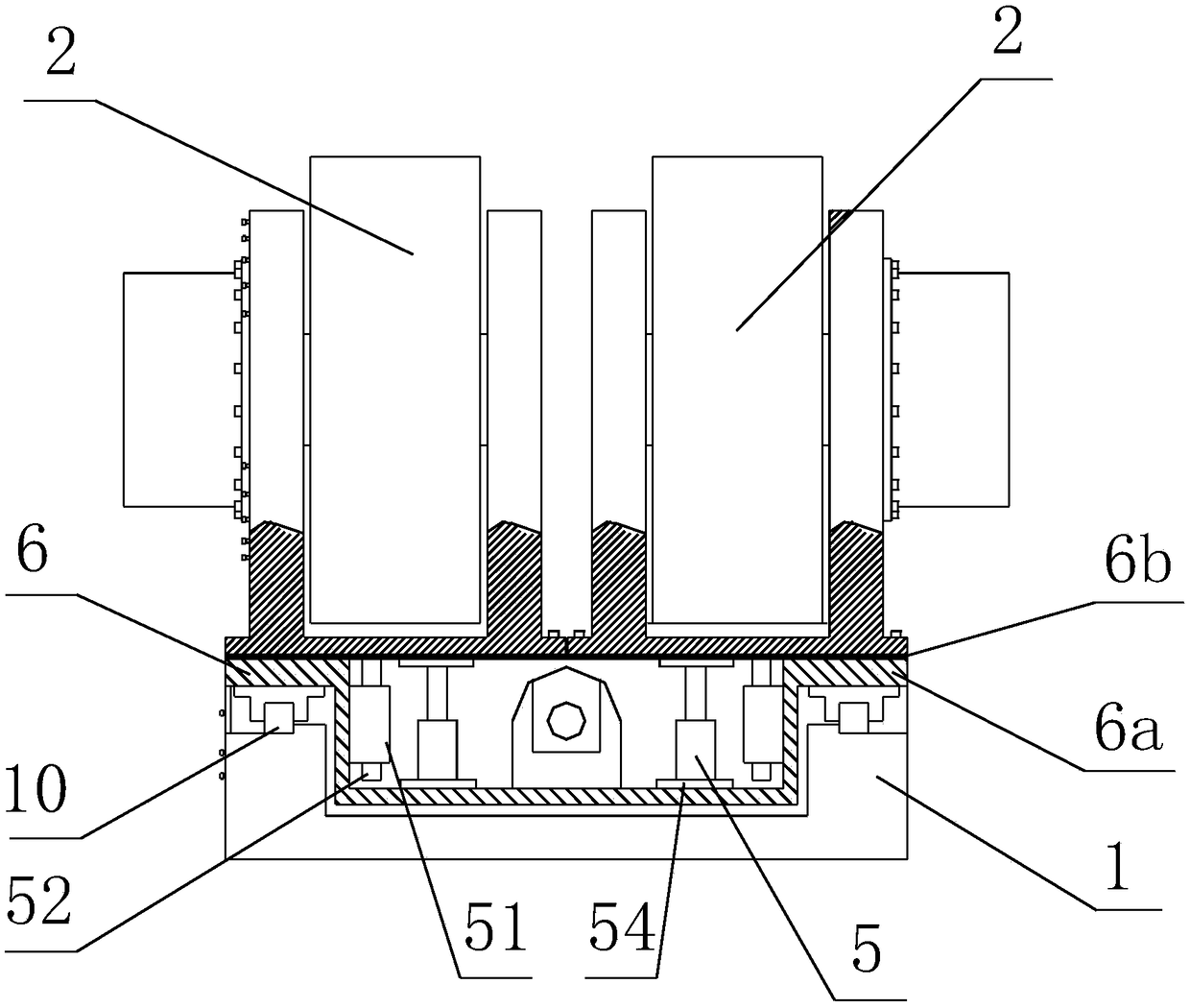
[0030] Such as Figure 1-6 As shown, a chassis dynamometer test bench driven by a permanent magnet synchronous motor includes a dynamometer 2, a base 1, a slide rail 10 arranged on the base, a pushing mechanism, a lifting mechanism 5, and a mounting seat 61 and mounting base 2 62; wherein mounting base 1 61 is fixed on one end of base 1, mounting base 2 62 is slidably installed on the slide rail 10 through the slider provided at its lower part; the dynamometer 2 includes four , work independently of each other, driven by a permanent magnet synchronous motor, and controlled by an all-electric inertia system; two of the dynamometers 2 are installed on the first mounting seat 61; the pushing mechanism is used to push the second mounting seat 62 along the The slide rail 10 moves; the lifting mechanism 5 is used to adjust the height of the dynamometer 2 from the ground.

[0031] Preferably, the dynamometer 2 includes a base 21, a main shaft 22, an encoder 24, a torque measuring de...

Embodiment 2

[0034] Such as Figure 7 As shown, a chassis dynamometer test bench driven by a permanent magnet synchronous motor includes a dynamometer 2, a base 1, a slide rail 10 arranged on the base, a pushing mechanism, a lifting mechanism 5, and a mounting seat 61 and mounting base 2 62; wherein mounting base 1 61 and mounting base 2 62 are all slidably installed on the slide rail 10 through the slide blocks provided at the respective lower parts; the dynamometer 2 includes four sets, which work independently of each other. Driven by a permanent magnet synchronous motor, controlled by an all-electric inertia system; two of the dynamometers 2 are installed on the first mounting base 61, and the other two are installed on the second mounting base 62; the pushing mechanism is used to push the The mounting base 6 moves along the slide rail 10; the lifting mechanism 5 is used to adjust the height of the dynamometer 2 from the ground.

[0035] Preferably, the dynamometer 2 includes a base 2...

Embodiment 3

[0038] Such as Figure 8 As shown, a chassis dynamometer test bench driven by a permanent magnet synchronous motor includes a dynamometer 2, a base 1, a slide rail 10 arranged on the base, a pushing mechanism, a lifting mechanism 5, and a mounting seat 61 , Mounting seat 2 62 and mounting seat 3 63; wherein mounting seat 1 61, mounting seat 2 62 and mounting seat 3 63 are all slidably installed on the slide rail 10 through the sliders provided at the respective lower parts; the dynamometer 2 includes six units, working independently of each other, driven by a permanent magnet synchronous motor, and controlled by an all-electric inertia system; two of the dynamometers 2 are installed on the same mounting base 1 61, and two are installed on the mounting base 2 62, the remaining two are installed on the second mounting base 62; the pushing mechanism is used to push the mounting base 6 to move along the slide rail 10; the lifting mechanism 5 is used to adjust the distance between ...


PUM


Abstract

The invention discloses a chassis dynamometer test bench driven by a permanent magnet synchronous motor. The chassis dynamometer test bench is characterized by comprising at least two dynamometers, abase, a slide rail arranged on the base, a pushing mechanism, a lifting mechanism and at least one mounting base slidably mounted the slide rail. The at least two dynamometers operate independently, are driven by the permanent magnet synchronous motor and are controlled by an all-electric inertia system. Every two dynamometers are installed on the same mounting base. The pushing mechanism is configured to push the mounting base along the slide rail. The lifting mechanism is configured to adjust the heights of the dynamometers to the ground. The chassis dynamometer test bench is capable of separately testing the wheels of a vehicle, and is simple in structure and adjustable in wheelbase.

Description

technical field [0001] The invention relates to the technical field of automobile testing equipment, in particular to a chassis dynamometer test bench driven by a permanent magnet synchronous motor. Background technique [0002] The chassis dynamometer is a kind of indoor bench test equipment used to test the performance of automobile power, multi-condition emission indicators, fuel indicators, etc. The automobile chassis dynamometer simulates the road surface through the roller, calculates the road simulation equation, and uses the loading device Carry out simulation to realize accurate simulation of various working conditions of the car. It can be used for loading and debugging of cars, and diagnosis of car failures under load conditions; it is compatible with five-gas analyzers, transmission smoke meters, engine tachometers, and computers The automatic control system forms a comprehensive measurement system to measure vehicle exhaust emissions under different working cond...

Claims


Application Information

Patent Timeline
Patent Type & Authority Applications(China)
IPC IPC(8): G01M17/007G01L5/00
CPCG01L5/0095G01M17/007
Inventor 黄诚徐伟刘汉光
Owner HUBEI HUANYEE ELECTROMAGNETIC EQUIP ENG TECH CO LTD
Why Eureka
Try Eureka