Energy storage transmission mechanism and rotary switch operating device using the energy storage transmission mechanism

A transmission mechanism and energy storage technology, which is applied to the power device inside the switch, electric switch, contact operating mechanism, etc., can solve the problems of poor operation feel, broken transmission parts, and short service life, so as to improve the effective power, Effects of reduced mechanical load and simple structure

Pending Publication Date: 2018-10-23
SHANGHAI LIANGXIN ELECTRICAL
View PDF9 Cites 5 Cited by
  • Summary
  • Abstract
  • Description
  • Claims
  • Application Information

AI Technical Summary

Problems solved by technology

However, they all convert the transmission action through a certain part of the transmission mechanism. In the case of long-term use, the transmission parts may break, resulting in a short service life; at the same time, due to the large operating force required for plastic deformation, the operation feels uncomfortable. good

Method used


Image

  • Energy storage transmission mechanism and rotary switch operating device using the energy storage transmission mechanism
  • Energy storage transmission mechanism and rotary switch operating device using the energy storage transmission mechanism
  • Energy storage transmission mechanism and rotary switch operating device using the energy storage transmission mechanism

Examples


Embodiment

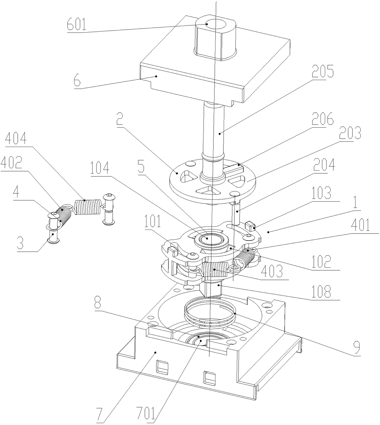
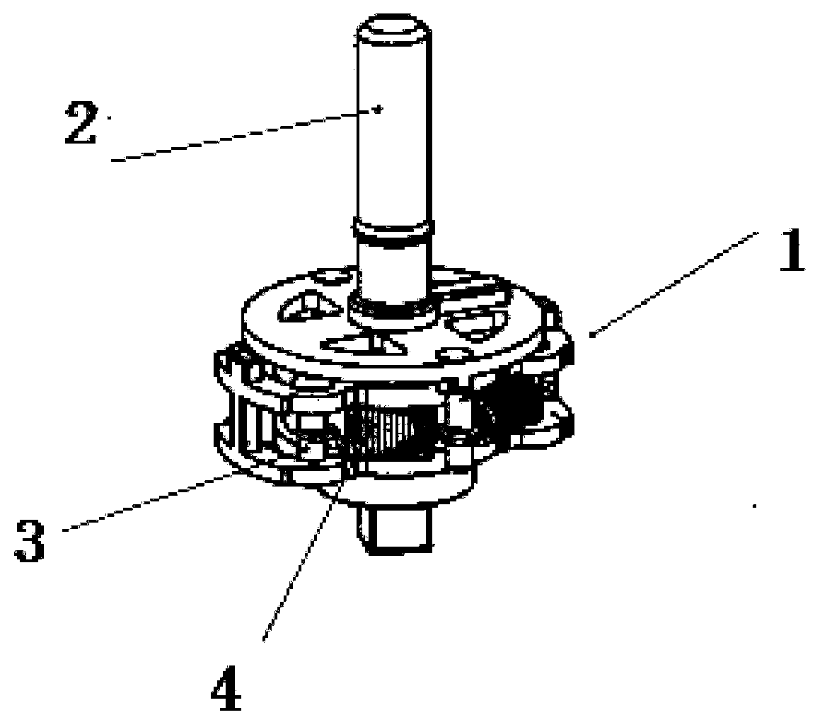
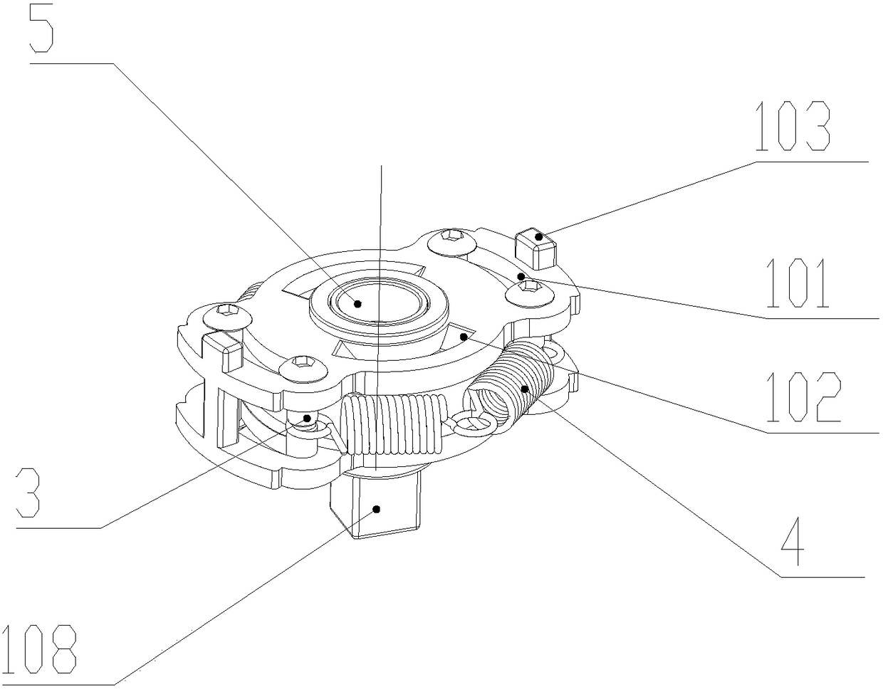
[0026] as attached Figure 2-7 As shown, the energy storage transmission mechanism includes a transmission shaft 1 and a drive shaft 2. The transmission shaft 1 is provided with 2 sliding holes 101, and 4 pairs of locking screws 3 are respectively installed in the preferably arc-shaped long waist hole. The two sliding holes 101 can slide, the upper end surface of the transmission shaft 1 is provided with two track slope grooves 102, and the inner end surface of the drive shaft 2 is provided with two tripping bosses 201 corresponding to the two track slope grooves 102 respectively. There are also two locking bosses 103 on the upper end surface of the shaft 1. The positioning shaft 202 protruding from the driving shaft 2 is installed on the shaft sleeve 5, and the shaft sleeve 5 is installed in the positioning hole 104 on the transmission shaft 1. Two locking buckles Boss 103 is located at the outer side of shaft disc 203 of drive shaft 2, one end of energy storage extension spr...


PUM


Abstract

An energy storage transmission mechanism comprises a transmission shaft (1) and a driving shaft (2). The mechanism is characterized in that the transmission shaft (1) is provided with a slide hole (101); a pair locking bolt (3) is installed in the slide hole (101) and can slide; the upper end surface of the transmission shaft (1) is provided with a track slope groove (102); the inner end surface of the driving shaft (2) is provided with a releasing convex platform (201) corresponding to the track slope groove (102); the upper end surface of the transmission shaft (1) is provided with a lockingconvex platform (103); a positioning shaft (202) which is stretched out of the driving shaft (2) is arranged in the positioning hole (104) of the transmission shaft (1); one end of an energy storagetension spring group (4) is installed on the pair locking bolt (3) and the other end is installed on a driving finger (204) stretched out of the driving shaft (2); and during the rotation process of the driving shaft (2), the driving finger (204) stretches the energy storage tension spring group (4) so that energy storage is performed. In the invention, the structure is simple, reliability is high, through a switch mechanism, the effective power of energy storage and transmission is increased, a mechanism load is reduced, and the motion reliability and the mechanical life of the mechanism areincreased and prolonged.

Description

technical field [0001] The invention belongs to the technical field of isolating switches, and in particular relates to an energy storage transmission mechanism and a rotary switch operating device using the energy storage transmission mechanism. Background technique [0002] The rotary switch has the function of turning on and off, and has a simple and compact structure, low manufacturing cost and small volume. For example, Chinese patent document CN205376364 U discloses an operating mechanism of a rotary switch, which includes an upper cover, a mounting base, a lever, an energy storage spring and a rotating shaft, and the rotating shaft is installed in the rotating shaft mounting groove of the mounting base and can be installed on the rotating shaft Rotate in the groove, the energy storage spring is installed in the groove of the inner cavity of the rotating shaft, the end of the energy storing spring is against the stopper in the groove, the upper end surface of the rotat...

Claims


Application Information

Patent Timeline
Patent Type & Authority Applications(China)
IPC IPC(8): H01H3/30H01H9/22H01H19/20
CPCH01H3/3005H01H9/22H01H19/20
Inventor 朱华张飞朱沈锋
Owner SHANGHAI LIANGXIN ELECTRICAL
Why Eureka
Try Eureka