
Emergency power source box and operation method thereof

An emergency power supply and storage battery technology, applied in the field of electric power, can solve problems that affect the stability of the power system, cannot be closed, and the power line cannot operate normally, and achieve the effects of ensuring stability, light weight, and simple operation

Pending Publication Date: 2018-10-23
STATE GRID CORP OF CHINA +2
View PDF3 Cites 2 Cited by
  • Summary
  • Abstract
  • Description
  • Claims
  • Application Information

AI Technical Summary

Problems solved by technology

In addition, the closing and opening time of the permanent magnet mechanism is stable and accurate, and the deviation is less than 0.5ms, which can solve the difficult problem of phase selection operation that is difficult to achieve with the general spring operating mechanism, and its superior performance can meet the needs of intelligent development of the power grid. The operating mechanism switch, the opening is controlled by the permanent magnet controller and the spring energy storage mechanism is added for backup, and the closing can only be realized by the controller driving the permanent magnet mechanism. When the line is powered off for a long time or the controller fails, the switch cannot be realized. The closing operation causes the power line to fail to operate normally and affects the stability of the power system. In actual production, it has occurred many times that the controller cannot be closed because the controller does not have enough power. Therefore, with the continuous development of the power industry, there is an urgent need for An emergency power box that is easy to transport and easy to operate to ensure the closing and opening operation of the permanent magnet circuit breaker after the power failure

Method used


Image

  • Emergency power source box and operation method thereof
  • Emergency power source box and operation method thereof

Examples


Embodiment Construction

[0019] The present invention will be further elaborated below in conjunction with the accompanying drawings and specific embodiments.

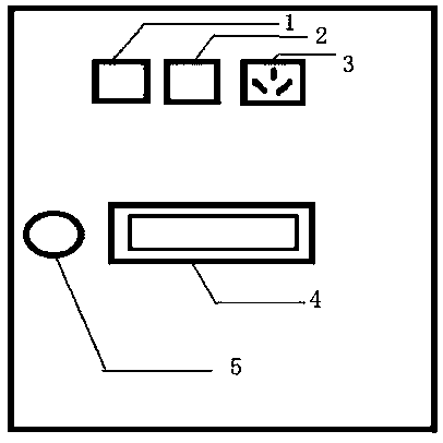
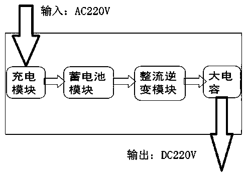
[0020] Such as figure 1 As shown, an emergency power supply box includes a charging module, a battery module, a rectification and inverter module, and a large capacitor module;

[0021] The charging module is used to convert AC 220V into battery charging voltage, and charge the battery;

[0022] The battery module is composed of two 12V lead-acid batteries connected in series for storing electric energy;

[0023] The rectification and inverter module is used to invert the 24V DC voltage into AC 24V through the electric bridge, after filtering, it is boosted to AC 220V through a step-up transformer, and then converted to DC 220V through the rectifier bridge;

[0024] The large capacitance module is composed of a capacitor with a capacity of 0.022F, which is used to store instantaneous electric energy and provide sufficient instantaneous opera...


PUM


Abstract

The invention discloses an emergency power source box and an operation method thereof. The emergency power source box comprises a charging module, a storage battery module, a rectification and inversion module and a large capacitance module; the charging module converts AC 220V into a charging voltage of a storage battery and charges the storage battery; the storage battery module is formed by connecting two lead acid batteries in the 12V DC voltages in series; the rectification and inversion module inverts the 24V DC voltage into an AC 24V via a bridge, and boosts the AC 24V into AC 220V by astep-up transformer after filtering, and converts the AC 220V into DC 220V by a rectifier bridge; and the large capacitance module stores instant electric energy, and provides a sufficient instant motion current for motion of a permanent magnetism switch. The power supply box is low in weight, simple in operation, safe and efficient, enables normal operation of power lines, ensures the stabilityof a power system, and avoids the frequent condition that closing cannot be carried out due to insufficient power of a controller in practical production.

Description

technical field [0001] The invention relates to the field of electric power technology, in particular to an emergency power supply box and an operating method thereof. Background technique [0002] The permanent magnet circuit breaker has few moving parts, no mechanism release and locking device, less than 80 parts, less than 12 operating parts, fewer fault sources, and greatly improved permanent mechanical reliability. In addition, the closing and opening time of the permanent magnet mechanism is stable and accurate, and the deviation is less than 0.5ms, which can solve the difficult problem of phase selection operation that is difficult to achieve with the general spring operating mechanism, and its superior performance can meet the needs of intelligent development of the power grid. The operating mechanism switch, the opening is controlled by the permanent magnet controller and the spring energy storage mechanism is added for backup, and the closing can only be realized b...

Claims


Application Information

Patent Timeline
Patent Type & Authority Applications(China)
IPC IPC(8): H02J9/06
CPCH02J9/061
Inventor 李新民相艳会宋翔林孙曙王中
Owner STATE GRID CORP OF CHINA
Learn More