Communication cable circuit detection system and detection method

A line detection and communication optical cable technology, applied in the field of communication, can solve the problems of the inability to monitor the slight disturbance of the optical fiber, the theft of the transmission information of the optical cable system, the sudden increase of the attenuation of the optical fiber and the connector attenuation, and the inability to damage the optical cable, etc., to achieve reliable and effective basic data Effects of supporting, reducing pressure and optical fiber monitoring costs, and shortening the monitoring cycle

Pending Publication Date: 2018-10-23
北京立成通科技有限公司
View PDF6 Cites 10 Cited by
  • Summary
  • Abstract
  • Description
  • Claims
  • Application Information

AI Technical Summary

Problems solved by technology

[0004] The current optical cable monitoring technology is mainly based on OTDR and optical power measurement methods, which can only measure static and very slow parameter changes, as well as fiber breakage in optical cables, fiber attenuation, and sudden increase in connector attenuation, etc., and cannot monitor small disturbances to optical fibers. As well as the theft of information transmitted by the optical cable system, it is also impossible to give an early warning of damage to the optical cable
On the other hand, the cost of existing optical cable line monitoring is relatively large

Method used


Image

  • Communication cable circuit detection system and detection method
  • Communication cable circuit detection system and detection method

Examples


Embodiment Construction

[0037] Exemplary embodiments, features, and aspects of the present invention will be described in detail below with reference to the accompanying drawings. The same reference numbers in the figures indicate functionally identical or similar elements. While various aspects of the embodiments are shown in drawings, the drawings are not necessarily drawn to scale unless specifically indicated.

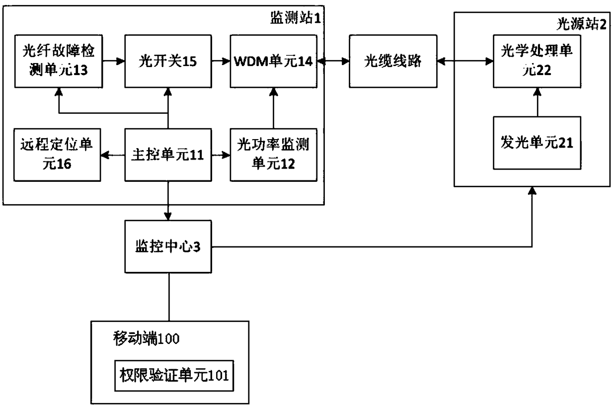
[0038] The invention provides a communication optical cable line detection system, such as figure 1 As shown, it includes a monitoring station 1, a mobile terminal 100, a light source station 2 and a monitoring center 3 that are connected to each other by communication,

[0039] The monitoring station 1 includes a main control unit 11, an optical power monitoring unit 12, an optical fiber fault detection unit 13, a multiplexing and demultiplexing unit 14, an optical switch 15, and a remote positioning unit 16, and the light source station 2 is provided with a light emitting unit 21 and a...


PUM


Abstract

The invention provides a communication cable circuit detection system comprising a monitoring station, a light source station and a monitoring center, wherein the monitoring station comprises a main control unit, an optical power monitoring unit, a cable fault detection unit, a wave combination and splitting unit, an optical switch and a remote positioning unit; the light source station is provided with a light emitting unit and an optical processing unit; the monitoring center, the optical power monitoring unit, the optical switch and the cable fault detection unit are separately in communication connection with the main control unit; the cable fault detection unit, the optical power monitoring unit, the optical processing unit and the wave combining and splitting unit are connected via optical fibers; the optical switch is arranged between the cable fault detection unit and the wave combining and splitting unit; the optical switch is configured to switch test light emitted by the cable fault detection unit in real time; and the wave combining and splitting unit is configured to perform partial wave combination on monitoring light received by the optical power monitoring unit andthe test light emitted by the cable fault detection unit.

Description

technical field [0001] The invention relates to the communication field, in particular to a communication optical cable detection system and detection method. Background technique [0002] In 1998, my country's former Ministry of Posts and Telecommunications promulgated "Technical Conditions for Optical Cable Line Automatic Monitoring System" YDN010-1998. In the next few years, manufacturers of optical cable monitoring systems have sprung up like mushrooms after a spring rain, and the automatic monitoring technology of optical cables has developed rapidly. Domestic operators have also experienced a climax of building optical cable monitoring systems. The computer automatic monitoring system of the transmission network has become an important means of fault location in the maintenance of trunk line optical cables in our country, and plays a huge role in the maintenance of the national trunk line network. [0003] Although the optical cable online automatic monitoring system ...

Claims


Application Information

Patent Timeline
Patent Type & Authority Applications(China)
IPC IPC(8): H04B10/077H04B10/079H04B10/032H04Q11/00H04L12/24H04L12/26
CPCH04B10/032H04B10/0771H04B10/0791H04B10/07955H04L41/069H04L43/045H04L43/06H04Q11/0005H04Q11/0062H04Q2011/0081
Inventor 李庆新
Owner 北京立成通科技有限公司
Why Eureka
Try Eureka