
Remote intelligent exchange management system for power optical cable fiber core

A technology of intelligent switching and management system, applied in the field of remote intelligent switching management system of power optical cable fiber core, can solve the problems of labor consumption, prolong fault recovery time, and long repair time, save manpower and material resources, improve adjustment efficiency, The effect of improving the monitoring level

Inactive Publication Date: 2020-04-28
STATE GRID CORP OF CHINA +1
View PDF4 Cites 1 Cited by
  • Summary
  • Abstract
  • Description
  • Claims
  • Application Information

AI Technical Summary

Problems solved by technology

[0004] 1) The optical network nodes are scattered in various substations, and the geographical distribution is very wide. When the optical cable fails and the route needs to be switched to other links, the maintenance personnel need to go to the site to manually jump the fiber, which greatly prolongs the working mode. recovery time
[0005] 2) Before deciding to switch the optical cable link, it is necessary to conduct on-site test of the optical cable channel performance parameters to ensure that the channel performance of the backup route is within the normal range. In this way, two groups of line personnel are required to conduct optical cable test one by one, which is time-consuming and labor-intensive.
[0006] 3) Communication dispatchers need to understand the configuration of optical cables in detail in troubleshooting and daily work, but the existing working mode will cause inaccurate and lagging configuration information, which will bring unnecessary troubles to communication dispatching work
[0007] In view of the above situation, the subject of remote automatic switching device for optical fiber core can transform the existing commonly used manual on-site optical link switching method into a remote control on-site automatic switching method, shorten the service recovery time when the optical cable fails, and improve the work of daily network adjustment. Efficiency, improve the accuracy, timeliness and integrity of optical cable resource data collection. With the intelligent development of the power grid, the existing optical fiber network will be difficult to meet the requirements of high reliability of transmission channels, and it will not be able to achieve professional lean management. As a communication The basic bearer network for transmission - the maintenance and repair of the optical cable network faces the following problems:
[0008] 1) There are many communication sites, the laying range of optical cables is wide, and the repair time is long;
[0009] 2) The acquisition of optical channel performance parameters is laborious and time-consuming;
[0010] 3) There is a large amount of management of optical fiber core resources, and the information is not updated in time;
[0011] 4) The workload of locating the fault point of the optical cable is heavy, and the welding of the fault breakpoint consumes manpower
[0012] At the same time, the operation and maintenance of the traditional optical cable network is still in the mode of manual maintenance and repair. The troublesome work, low efficiency, and constraints of the geographical environment have seriously affected the fast, safe, simple and reliable communication dispatching of the communication network. Requirements, for this reason, propose a kind of power optical cable fiber core remote intelligent exchange management system to solve the above problems

Method used


Image

  • Remote intelligent exchange management system for power optical cable fiber core
  • Remote intelligent exchange management system for power optical cable fiber core
  • Remote intelligent exchange management system for power optical cable fiber core

Examples


Embodiment Construction

[0033] The following will clearly and completely describe the technical solutions in the embodiments of the present invention with reference to the accompanying drawings in the embodiments of the present invention. Obviously, the described embodiments are only some, not all, embodiments of the present invention. Based on the embodiments of the present invention, all other embodiments obtained by persons of ordinary skill in the art without making creative efforts belong to the protection scope of the present invention.

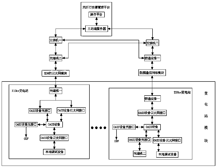
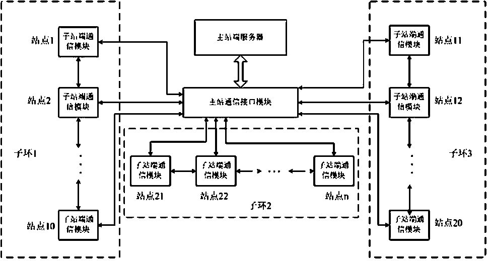
[0034] see Figure 1-6, the present invention discloses a remote intelligent exchange management system for power optical fiber cores, including an optical fiber core resource management platform and a substation module, the substation module includes a 110kv substation and a 220kv substation, and the 110kv substation is equipped with an OASS device inside, The output end of the OASS equipment one is bidirectionally electrically connected to the input end of t...


PUM


Abstract

The invention discloses a remote intelligent exchange management system for a power optical cable fiber core, and relates to the technical field of optical fiber communication. The system comprises anoptical fiber core resource management platform and a transformer substation module. The transformer substation module comprises a 110kv transformer substation and a 220kv transformer substation. According to the invention, OTDR modules are configured in various bureau stations, 220kV substations and 110kV substations, so testing of all optical cable spare fiber cores in the bureau stations can be realized; the remote fiber jumping function of the self-configured terminal can be utilized to realize the chain test of the downstream communication optical cable; the OTDR module of each hub siteis matched with each 110kV self-configuration terminal for use, so the performance testing of all communication optical cable spare fiber cores in a transformer area can be completed; because fiber jumping work can be remotely operated and implemented at an operation terminal, the field operation is not needed, the manpower and material resources are greatly saved, the monitoring period can also be shortened, and therefore the communication optical cable monitoring level is greatly improved.

Description

technical field [0001] The invention relates to the technical field of optical fiber communication, in particular to a remote intelligent exchange management system for power optical cable cores. Background technique [0002] Optical fiber communication is the main implementation of power communication systems. Affected by factors such as disaster weather, external force damage, and optical cable aging, optical cable failures occur from time to time. When an optical cable failure occurs, it is necessary to find a reliable route in the shortest time and adjust the optical communication. In the network operation mode, the affected optical link is switched to other normal operating optical cables. At present, the work of testing new routing channel parameters, optical link switching, and optical link routing data collection needs to be done manually on site, which is time-consuming and laborious. . The contradiction between the sharp increase in the workload of optical cable o...

Claims


Application Information

Patent Timeline
Patent Type & Authority Applications(China)
IPC IPC(8): H04Q11/00H04B10/032H04B10/071H04B10/077
CPCH04B10/032H04B10/071H04B10/0771H04Q11/0005H04Q11/0062H04Q2011/0081H04Q2011/0083
Inventor 尚春山张光亚赵广霏董建雄贾多斌赵莉莉高峰王鹏源
Owner STATE GRID CORP OF CHINA
Learn More