
Stator, motor, and compressor

A technology for stators and motors, which can be applied to electromechanical devices, control mechanical energy, casings/covers/supports, etc., and can solve problems such as short circuits

Active Publication Date: 2018-10-23
NIDEC CORP
View PDF8 Cites 19 Cited by
  • Summary
  • Abstract
  • Description
  • Claims
  • Application Information

AI Technical Summary

Problems solved by technology

However, if the gap between parts is reduced in the stator of the motor, the lead wire drawn from the coil may come into contact with the coil or a metal case, etc., causing a short circuit

Method used


Image

  • Stator, motor, and compressor
  • Stator, motor, and compressor
  • Stator, motor, and compressor

Examples


Embodiment Construction

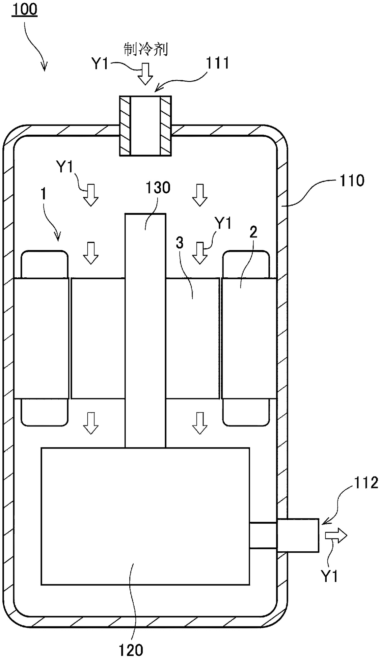
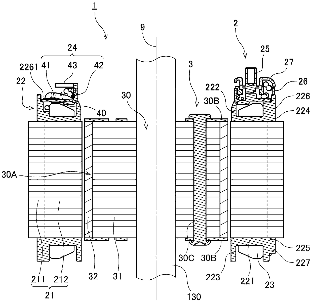
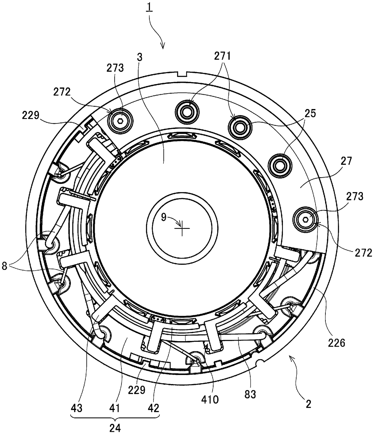
[0027] Hereinafter, exemplary embodiments of the present invention will be described with reference to the drawings. In addition, in this application, the direction parallel to the central axis of the motor is called "axial direction", the direction perpendicular to the central axis of the motor is called "radial direction", and the direction along the central axis of the motor is called "radial". The direction is called "circumferential". However, the above-mentioned "parallel direction" also includes substantially parallel directions. In addition, the above-mentioned "vertical direction" also includes a substantially vertical direction.

[0028] In addition, in the present application, the shape and positional relationship of each part will be described with the axial direction being the up-down direction and the guide member side facing up with respect to the coil. However, it does not mean that the orientation of the stator, motor, and compressor of the present invention...


PUM


Abstract

This stator has a plurality of lead lines extending from coils toward the upper side and a guide member for supporting the lead lines on the upper side from the coils. The guide member is an insulatorand has a lower plate portion, an inner wall portion, and an upper plate portion, wherein said lower plate portion circularly extends around the central axis, said inner wall portion extends upward from the inner circumference portion of the lower plate portion, and said upper plate portion extends from the inner wall portion toward the radial direction outside. There is a single lead-line housing space on the upper side of the lower plate portion, the lower side of the upper plate portion, and the radial direction outside of the inner wall portion. In the lead-line housing space, the lead lines are disposed along the inner wall portion in a circumferential direction. This makes it possible to arrange the lead lines in a compact manner without requiring a bus bar while ensuring the insulation between the coils and the lead lines. This also satisfies both the size reduction of the stator and the insulation properties of the lead lines. Further, winding the lead lines on the inner wallportion enables the lead lines to be easily disposed between the lower plate portion and the upper plate portion.

Description

technical field [0001] The invention relates to stators, motors and compressors. Background technique [0002] In recent years, motors have been required to be smaller and thinner. In order to reduce the size of the motor, for example, it is considered to reduce the gap between parts in the motor. However, if the gap between the parts is reduced in the stator of the motor, the lead wire drawn from the coil may come into contact with the coil or a metal case, and short circuit may occur. Therefore, it is necessary to arrange an insulating member between the lead wire drawn from the coil and other conductive members inside the motor. [0003] For example, Japanese Patent Application Laid-Open No. 2014-187797 describes a structure in which a holder portion is arranged at an axial end portion of a stator core, and a plurality of conducting wires are arranged in the holder portion. These lead wires include a lead wire for power supply that supplies current from an external pow...

Claims


Application Information

Patent Timeline
Patent Type & Authority Applications(China)
IPC IPC(8): H02K3/38H02K3/50
CPCH02K3/28H02K3/522H02K5/12H02K5/225H02K2203/06B60H1/3222H02K1/146H02K1/274H02K3/18H02K3/30H02K3/325H02K7/14
Inventor 冈本俊哉川岛彰太青野真乡右田贵之
Owner NIDEC CORP
Learn More