
Method and device for controlling uplink transmission power, base station and user equipment

A technology of transmission power and user equipment, applied in the field of communication, can solve problems such as high transmission power, human hazards, wireless signal radiation exceeding the specific absorption rate, etc.

Active Publication Date: 2018-10-23
BEIJING XIAOMI MOBILE SOFTWARE CO LTD
View PDF5 Cites 27 Cited by
  • Summary
  • Abstract
  • Description
  • Claims
  • Application Information

AI Technical Summary

Problems solved by technology

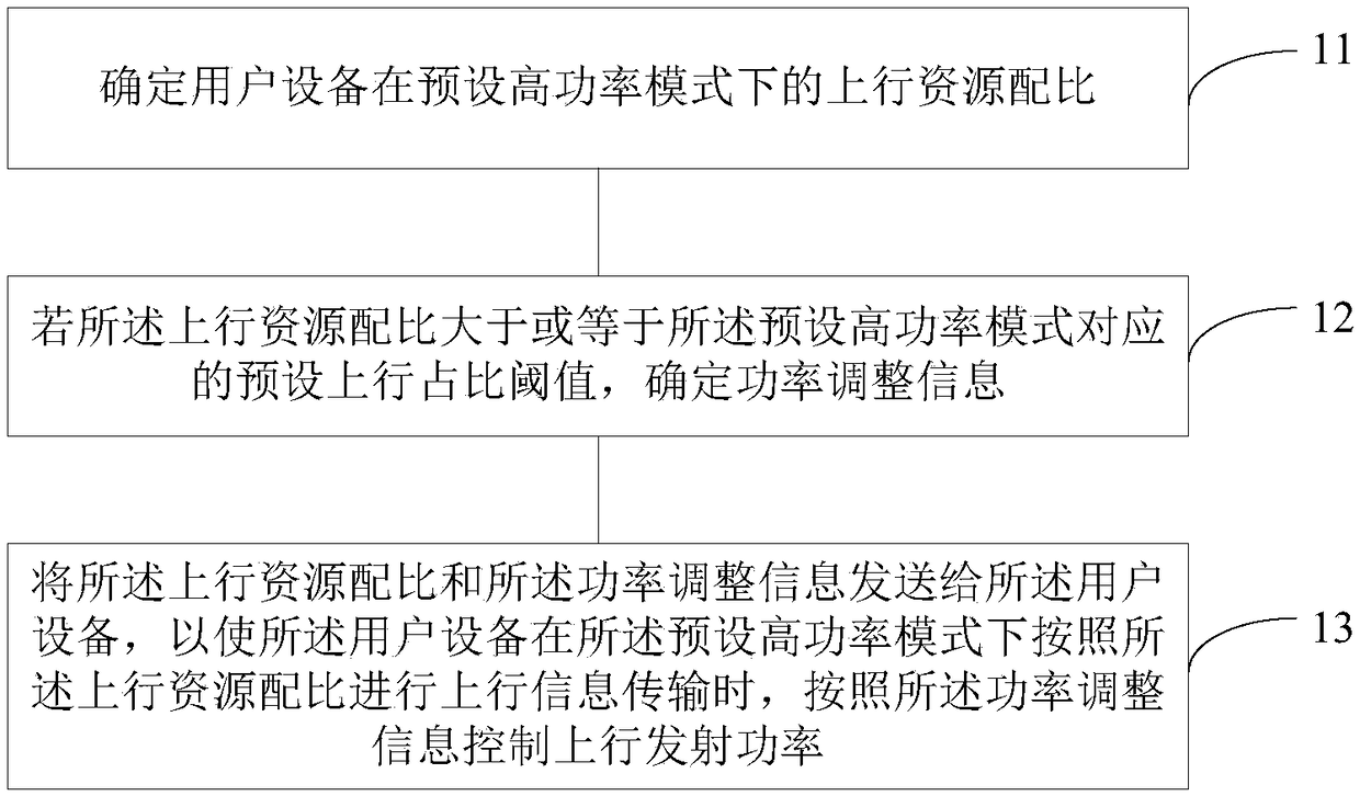
[0003] Due to the high transmit power of the UE in the preset high transmit power mode, if the base station configures resources for the UE in the HPUE mode, the configured uplink and downlink resource ratio is not appropriate, which will cause the radio signal radiation of the UE in the HPUE mode If the amount exceeds the SAR measurement standard, it will cause harm to the human body

Method used


Image

  • Method and device for controlling uplink transmission power, base station and user equipment
  • Method and device for controlling uplink transmission power, base station and user equipment
  • Method and device for controlling uplink transmission power, base station and user equipment

Examples


Embodiment approach 1

[0229] Embodiment 1: Subtract the preset power offset from the original maximum transmit power of the UE to obtain the corrected maximum transmit power

[0230] Assuming P CMAX0 Indicates the original maximum transmit power, then the corrected maximum transmit power P CMAX It can be represented by the following formula (2):

[0231] P CMAX =P CMAX0 -Delta_P CMAX (R UL )...(Formula 2)

[0232] Among them, Delta_P CMAX (R UL ) represents the aforementioned preset correction amount, which may also be referred to as a power offset. Delta_P CMAX (R UL ) will follow the uplink resource ratio R UL The increase increases, that is, Delta_P CMAX (R UL ) and R UL Positive correlation.

[0233] In a TDD (Time Division Duplexing, Time Division Duplexing) system, such as an LTE TDD system, the uplink resource ratio R UL It can be expressed as: uplink transmission time t_UL per unit time, where the above unit time represents the duration of a unit information transmission tim...

Embodiment approach 2

[0238] Embodiment 2: multiply the original maximum transmit power of the UE by a preset correction factor to obtain the corrected maximum transmit power, which can be expressed by the following formula (4):

[0239] P CMAX = alpha_P CMAX (R UL )*P CMAX0 ... (Formula 4)

[0240] Among them, alpha_P CMAX (R UL ) represents the above-mentioned preset correction factor, and the value range is (0, 1). alpha_P CMAX (R UL ) will follow the uplink resource ratio R UL increase and decrease.

[0241] Similarly, in a TDD system, if the uplink resource ratio R UL Expressed as: uplink transmission time t_UL per unit time, the above formula (4) can be specifically expressed as the following formula (5):

[0242] P CMAX = alpha_P CMAX (t_UL)*P CMAX0 ... (Formula 5)

[0243] Similarly, the maximum transmit power correction factor alpha_P CMAX The value range of (t_UL) is a natural number of (0, 1), and alpha_P CMAX The value of (t_UL) decreases with the increase of t_UL.

[...


PUM


Abstract

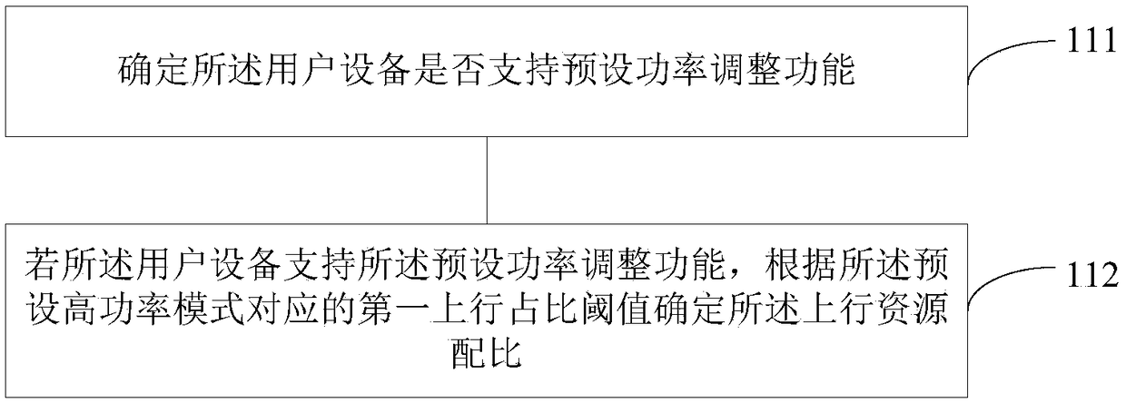
The invention provides a method and device for controlling uplink transmission power, a base station and user equipment, wherein the method comprises the steps of determining the uplink resource ratioof the user equipment in a preset high-power mode; if the uplink resource allocation ratio is larger than or equal to a preset uplink duty ratio threshold value corresponding to the preset high-powermode, determining power adjustment information; sending the uplink resource allocation and the power adjustment information to the user equipment, so that the user equipment performs uplink information transmission according to the uplink resource proportion in the preset high-power mode; controlling the uplink transmission power according to the power adjustment information. The method for controlling uplink transmission power provided by the invention is adopted, when the UE is configured to perform uplink information transmission according to a higher uplink resource allocation ratio, theUE can be configured to adjust the uplink transmission power according to the power adjustment information, so that the exceeding of the SAR is effectively avoided., meanwhile, the uplink informationtransmission capability of the UE in a preset high-power transmission mode is improved.

Description

technical field [0001] The present disclosure relates to the field of communication technologies, and in particular to a method and device for controlling uplink transmission power, a base station, and user equipment. Background technique [0002] When 5G NR (New Radio) and LTE (Long Term Evoluttion, long-term evolution) are deployed, the uplink transmit power of UE (User Equipment, user equipment) is graded by power class, for example, powerclass 3 is 23dBm, which is a typical UE Uplink transmit power. In some application scenarios, for example, when the UE works in a higher frequency band such as 3.5GHz, in order to ensure the increase of uplink coverage, the UE needs to have a higher uplink transmission power, such as 26dBm or powerclass 2, etc., and enter the preset high power power class mode A UE that transmits is called a High Power UE (HPUE). [0003] Due to the high transmit power of the UE in the preset high transmit power mode, if the base station configures res...

Claims


Application Information

Patent Timeline
Patent Type & Authority Applications(China)
IPC IPC(8): H04W52/08H04W52/36
CPCH04W52/08H04W52/36H04W52/365H04W52/146H04W52/367H04W52/288H04W8/24H04L1/0003
Inventor 周珏嘉
Owner BEIJING XIAOMI MOBILE SOFTWARE CO LTD
Learn More