Eureka AIR delivers breakthrough ideas for toughest innovation challenges, trusted by R&D personnel around the world.

Rope slow descending device

A rope and slow descent technology, applied in life-saving equipment, building rescue, etc., can solve the problems of easy loss of control, peeling, rope breaking, etc., and achieve the effects of not easy stress concentration, simple operation logic, and reliable mechanical structure.

Pending Publication Date: 2018-10-26
INNER MONGOLIA UNIV OF TECH
View PDF7 Cites 2 Cited by
  • Summary
  • Abstract
  • Description
  • Claims
  • Application Information

AI Technical Summary

Problems solved by technology

[0003] The rope descent device is one of the hot research topics of high-rise escape facilities. A good rope descent device should have the following characteristics: First, it should be easy to use and easy to learn. Ordinary people have not received special training. If the operation of the rope descent device is cumbersome, it will undoubtedly delay the escape time; second, the descending speed should not be too fast, otherwise it is easy to lose control; third, it must be stable and reliable enough, which requires the descent device itself The mechanical structure is reliable, and the operation logic is also required to be stable and reliable. Even if a certain operation error occurs, it can be rescued through simple operations, so that it will not slide down at a very fast speed or cause the danger of falling; The rope used during descent should not produce excessive stress concentration, and the contact area with the rope should be as large as possible during deceleration or sudden braking, otherwise the rope will be easily broken or peeled, causing danger

Method used


Image

  • Rope slow descending device
  • Rope slow descending device
  • Rope slow descending device

Examples


Embodiment Construction

[0035] The present invention will be further described below in conjunction with the embodiments of the present invention and the accompanying drawings.

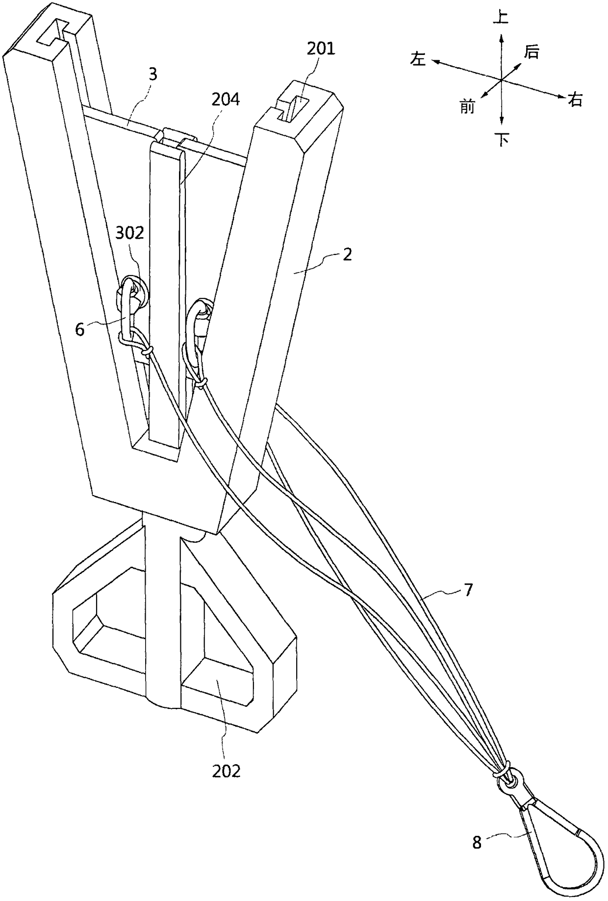
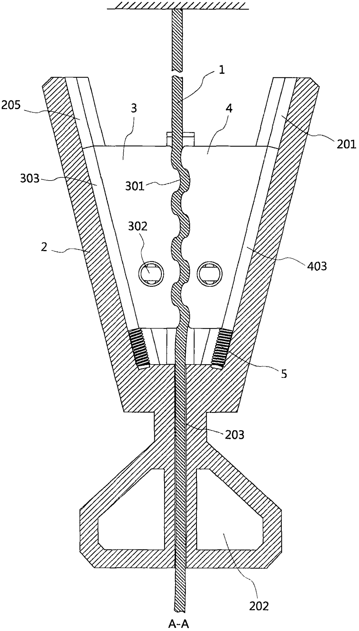
[0036] Such as figure 1 , 2 , 3, and 4, a rope descent device of the present invention includes a base body 2, a left movable part 3, a right movable part 4, a load-bearing rope 1, and an elastic body 5. The base body 2 is a V-shaped structure, including a left The chute 205 and the right chute 201, the left chute 205 and the right chute 201 are symmetrical to each other with the V-shaped center line of the base body 2 as the axis of symmetry, and the left movable part 3 and the right movable part 4 are provided with guide sliders 303, the guide slider 303 of the left movable part 3 is installed in the left chute 205 of the base body 2, and connected with the base body 2 through the elastic body 5, the guide slider 403 of the right movable part 4 is installed It is in the right slide groove 201 of the base body 2 and conne...


PUM


Abstract

The invention relates to the field of security and protection, in particular to a rope slow descending device. The rope slow descending device comprises a base body, a left movable portion, a right movable portion, a force bearing rope and elastic bodies; the base body is of a V-shaped structure and comprises a left sliding groove and a right sliding groove which are mutually symmetric with the V-shaped center line of the base body as the axis of symmetry; guide slide blocks are arranged on the left movable portion and the right movable portion; the guide slide block of the left movable portion is installed in the left sliding groove of the base body and is connected with the base body through the corresponding elastic body; and the guide slide block of the right movable portion is installed in the right sliding groove of the base body and connected with the base body through the corresponding elastic body. Operation is logic and simple, the mechanical structure is reliable, stress concentration of a slowly descending rope is not likely to be generated, the highest descending speed can be restrained by the mechanical structure features, glide being close to a free falling body doesnot occur, and the rope slow descending device is a reliable high-rise escape device.

Description

technical field [0001] The invention relates to the security field, in particular to a rope slow-down device. Background technique [0002] In the process of urbanization, high-rise buildings are becoming more and more common. The higher the floor, the more difficult it is to resist various disasters, especially when natural or man-made disasters such as water, fire, poison, and earthquake occur, often accompanied by elevator power failure or escape channel failure. Evacuation and rescue just become very difficult, often need to use high-rise escape facilities, high-rise escape facilities can help the people affected by the disaster escape from dangerous buildings in time, and protect the safety of people's lives and property. [0003] The rope descent device is one of the hot research topics of high-rise escape facilities. A good rope descent device should have the following characteristics: First, it should be easy to use and easy to learn. Ordinary people have not receiv...

Claims


Application Information

Patent Timeline
IPC IPC(8): A62B1/06A62B1/18
CPCA62B1/06A62B1/18
Inventor 张楠周洁刘佳
Owner INNER MONGOLIA UNIV OF TECH
Why Eureka
Eureka Blog
Learn More