PWM control signal generation method, circuit and chip

A technology for controlling signals and generating methods, applied in the direction of pulse duration/width modulation, etc., can solve the problems of high-precision PWM signal difficulty, and achieve the effect of simplifying design difficulty, improving processing speed, and simple operation

Active Publication Date: 2020-07-14
SUZHOU KEDA TECH
View PDF3 Cites 2 Cited by
  • Summary
  • Abstract
  • Description
  • Claims
  • Application Information

AI Technical Summary

Problems solved by technology

[0004] Therefore, the technical problem to be solved by the present invention is to overcome the defect that it is difficult to obtain a high-precision PWM signal in the prior art, thereby providing a generation method, circuit and chip of a PWM control signal

Method used


Image

  • PWM control signal generation method, circuit and chip
  • PWM control signal generation method, circuit and chip
  • PWM control signal generation method, circuit and chip

Examples


Embodiment

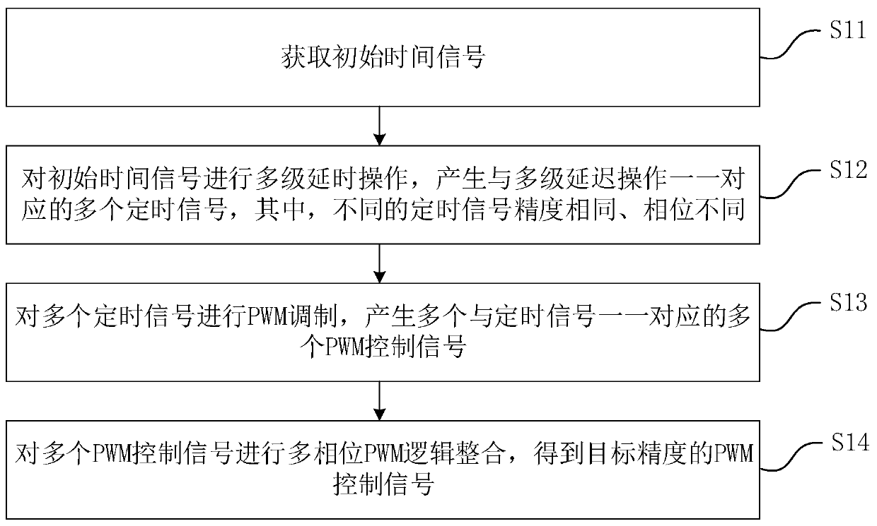
[0034] This embodiment provides a method for generating a PWM control signal, which is applied to a digital circuit that realizes pulse width modulation, such as figure 1 As shown, the method includes the following steps:

[0035] S11. Acquire an initial time signal.

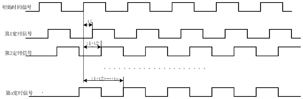
[0036] Exemplarily, the initial time signal is a low-precision time signal. The low-precision time signal takes a square wave signal as an example, and the accuracy corresponds to the duty cycle of the square wave signal, such as image 3 The square wave signal shown has an accuracy of T0. The low-precision time signal can be obtained according to the on / off time of the transistor or MOS tube. The present application does not limit the manner of acquiring the initial time signal, and those skilled in the art can determine it according to actual needs.

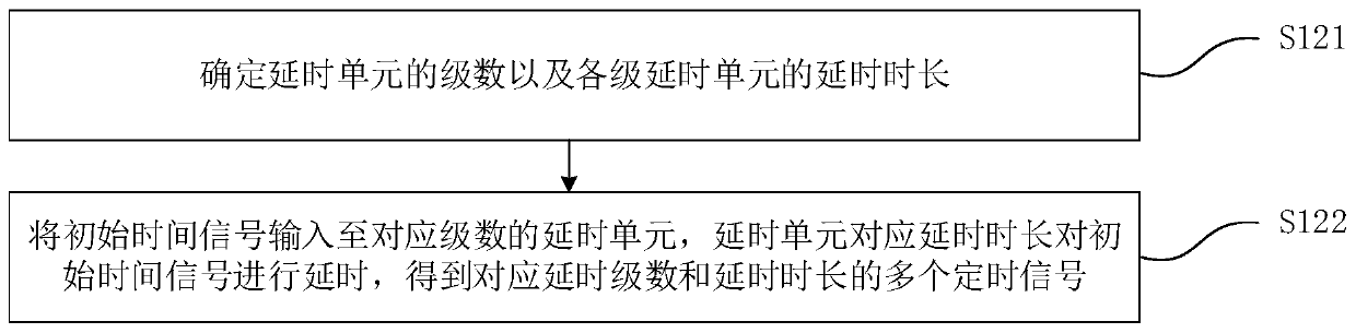
[0037] S12, performing a multi-stage delay operation on the initial time signal to generate a plurality of timing signals corresponding to the multi-stage de...


PUM


Abstract

The invention discloses a PWM control signal generation method and circuit and a chip The method comprises the steps: obtaining an initial time signal; performing multi-stage delay operation on the initial time signal to generate a plurality of timing signals in one-to-one correspondence with the multi-stage delay operation, wherein different timing signals have the same precision and different phases; carrying out PWM modulation on the plurality of timing signals to generate a plurality of PWM control signals in one-to-one correspondence with the timing signals; performing multi-phase PWM logic integration on the plurality of PWM control signals to obtain PWM control signals with target precision. Through the implementation of the invention, the high-precision PWM control signal with anypulse width can be obtained through the low-precision clock signal, the operation is simple, the design difficulty of a digital circuit is simplified, and the implementation difficulty of the digitalcircuit is reduced.

Description

technical field [0001] The invention relates to the technical field of digital circuits, in particular to a method for generating a PWM control signal, a circuit and a chip. Background technique [0002] Pulse width modulation (PWM), as an effective analog control method that uses digital signals to control analog circuits, has been widely used in many application fields, such as measurement, communication, various power control and conversion, etc. technical field. PWM can modulate the bias of the transistor base or MOS transistor gate according to the change of the corresponding load, so as to realize the change of the conduction time of the transistor or MOS transistor, so as to realize the change of the output of the switching regulated power supply or the constant current source. [0003] With the development of electronic technology, a variety of pulse width modulation techniques have emerged, including: phase voltage control PWM, pulse width PWM method, random PWM, S...

Claims


Application Information

Patent Timeline
Patent Type & Authority Applications(China)
IPC IPC(8): H03K7/08
CPCH03K7/08
Inventor 白涛周浩曹李军
Owner SUZHOU KEDA TECH
Why Eureka
Try Eureka