Eureka AIR delivers breakthrough ideas for toughest innovation challenges, trusted by R&D personnel around the world.

Cavity-free composite heat-insulation thermal-break bridge structure and construction method

A composite thermal insulation and structural body technology, applied in thermal insulation, building components, building structures, etc., can solve the problems of hidden fire hazards, increased cost of building exterior wall insulation, etc., and achieve the effect of meeting fire protection requirements and solving thermal bridge phenomena

Pending Publication Date: 2018-10-26
沈阳领创建筑科技有限公司
View PDF9 Cites 6 Cited by
  • Summary
  • Abstract
  • Description
  • Claims
  • Application Information

AI Technical Summary

Problems solved by technology

[0003] Building exterior wall insulation is an important part of building energy conservation, and it is also an important part of building fire protection. The insulation materials used for building exterior wall insulation can be divided into A-level insulation materials and B-level insulation materials. If A-level insulation materials are used , it will lead to an increase in the cost of building exterior wall insulation, and if B-grade insulation materials are used, it will cause fire hazards

Method used


Image

  • Cavity-free composite heat-insulation thermal-break bridge structure and construction method
  • Cavity-free composite heat-insulation thermal-break bridge structure and construction method

Examples


Embodiment Construction

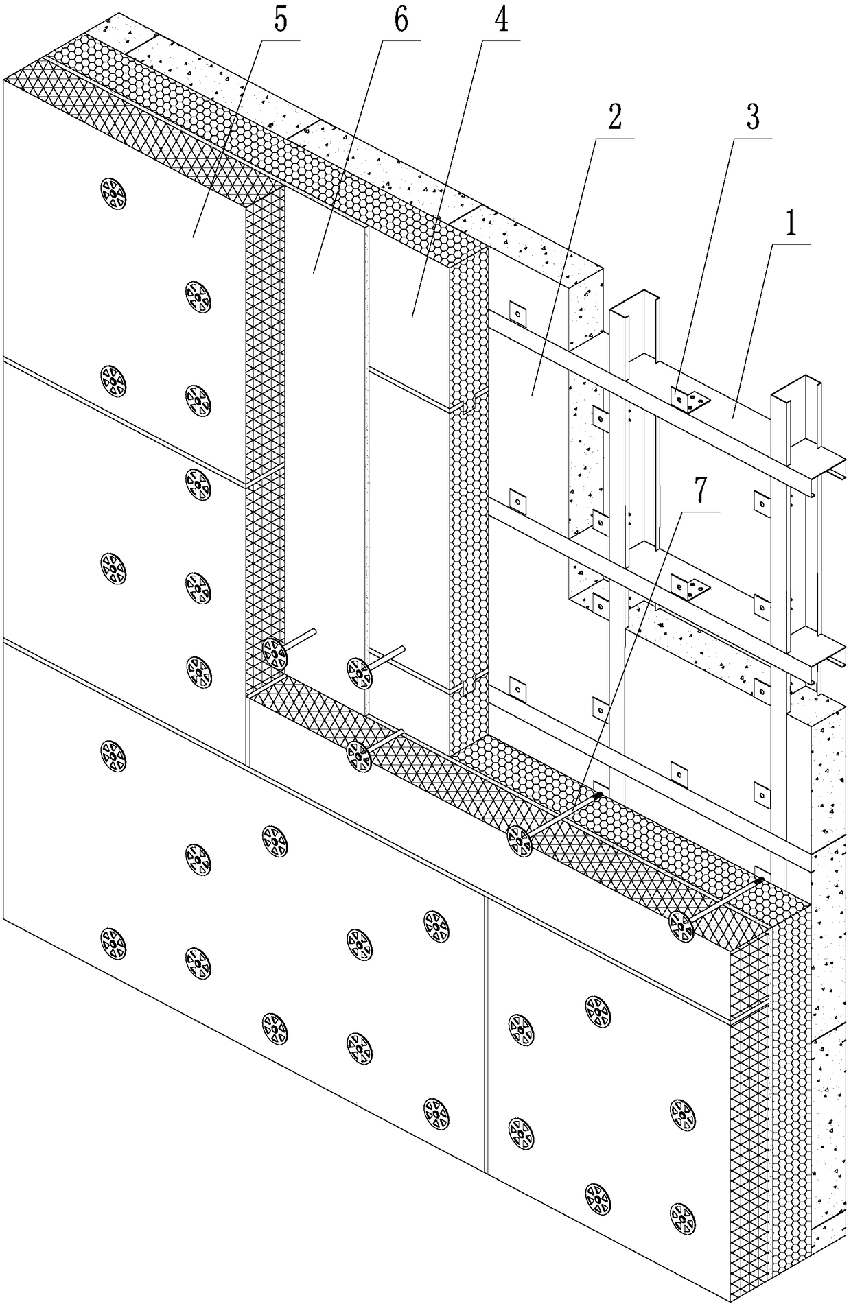
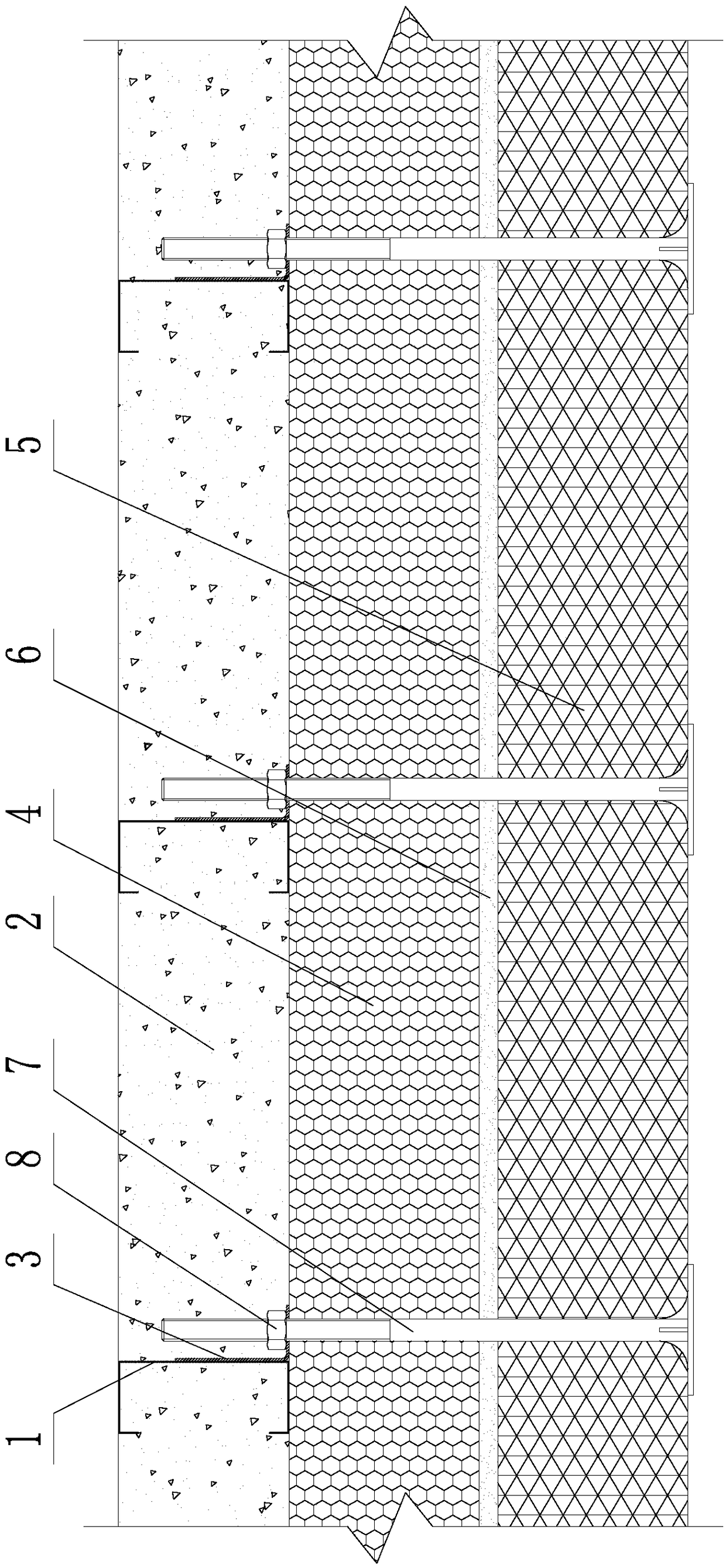
[0027] The present invention will be further described in detail below in conjunction with the accompanying drawings and specific embodiments.

[0028] Such as figure 1 , 2 As shown, a cavity-free composite thermal insulation bridge structure includes an inner structural layer, an intermediate thermal insulation layer and an outer protective layer; the inner structural layer includes a light steel skeleton 1, a lightweight concrete wall 2 and an adapter frame 3. Both the light steel frame 1 and the adapter frame 3 are poured in the lightweight concrete wall 2, and the adapter frame 3 is fixedly connected to the light steel frame 1; the middle insulation layer includes B1 / B2 grade insulation materials 4, B1 The / B2 grade thermal insulation material 4 is a block plate, and the middle thermal insulation layer is composed of several pieces of B1 / B2 grade thermal insulation material 4; 5 pieces of non-combustible materials are spliced ​​together; an adhesive layer 6 is provided b...


PUM


Abstract

The invention provides a cavity-free composite heat-insulation thermal-break bridge structure and a construction method. The thermal-break bridge structure comprises an inner structure layer, a middleheat-insulation layer and an outer protecting layer; the inner structure layer comprises a light steel framework, a light concrete wall body and a connecting rack; the light steel framework and the connecting rack are poured in the light concrete wall body; the connecting rack is fixedly connected to the light steel framework; the middle heat-insulation layer consists of a plurality of B1 / B2-level heat-insulation materials which are connected; the outer protecting layer consists of a plurality of incombustible materials which are connected; the outer protecting layer and the middle heat-insulation layer are attached to be in a cavity-free state; and the outer protecting layer is fixedly connected with the inner structure layer through thermal-break bridge bolts. The construction method comprises the following steps: assembling the light steel framework and mounting the connecting rack; assembling the B1 / B2-level heat-insulation materials to form the middle heat-insulation layer; coating an adhesion layer; assembling incombustible materials to form the outer protecting layer; successively drilling out the middle heat-insulation layer, the adhesion layer and the outer protecting layer by using a drill bit; and penetrating a thermal-break bridge bolt in drilling holes, and fixedly connecting the thermal-break bridge bolt with the connecting rack; and pouring light concrete in theinner structure layer until the light concrete is solidified.

Description

technical field [0001] The invention belongs to the technical field of construction engineering, in particular to a cavity-free composite thermal insulation bridge structure and a construction method. Background technique [0002] Building thermal bridges refer to reinforced concrete or metal beams / columns / ribs / fittings and other parts in the enclosure structures such as exterior walls and roofs. Due to the strong heat transfer capacity of these parts, the heat flow is relatively dense, and the inner surface temperature is relatively low. called a thermal bridge. [0003] Building exterior wall insulation is an important part of building energy conservation, and it is also an important part of building fire protection. The insulation materials used for building exterior wall insulation can be divided into A-level insulation materials and B-level insulation materials. If A-level insulation materials are used , it will lead to an increase in the cost of building exterior wall...

Claims


Application Information

Patent Timeline
Patent Type & Authority Applications(China)
IPC IPC(8): E04B1/76
CPCE04B1/7608
Inventor 夏晓东
Owner 沈阳领创建筑科技有限公司
Why Eureka
Eureka Blog
Learn More