Friction transmission stepless speed change device

A continuously variable transmission device and friction transmission technology, applied in the field of transmission, can solve the problems of metal belts being easily damaged, limited in strength, unable to bear large loads, etc., and achieve the effect of precise control process and guaranteed reliability

Active Publication Date: 2018-10-26
XUZHOU COLLEGE OF INDAL TECH
View PDF12 Cites 3 Cited by
  • Summary
  • Abstract
  • Description
  • Claims
  • Application Information

AI Technical Summary

Problems solved by technology

[0004] The disadvantage of the common metal belt CVT is that the metal belt is easily damaged, limited by its strength, and

Method used


Image

  • Friction transmission stepless speed change device
  • Friction transmission stepless speed change device
  • Friction transmission stepless speed change device

Examples


Example Embodiment

[0025] The present invention will be further described below in conjunction with the accompanying drawings.

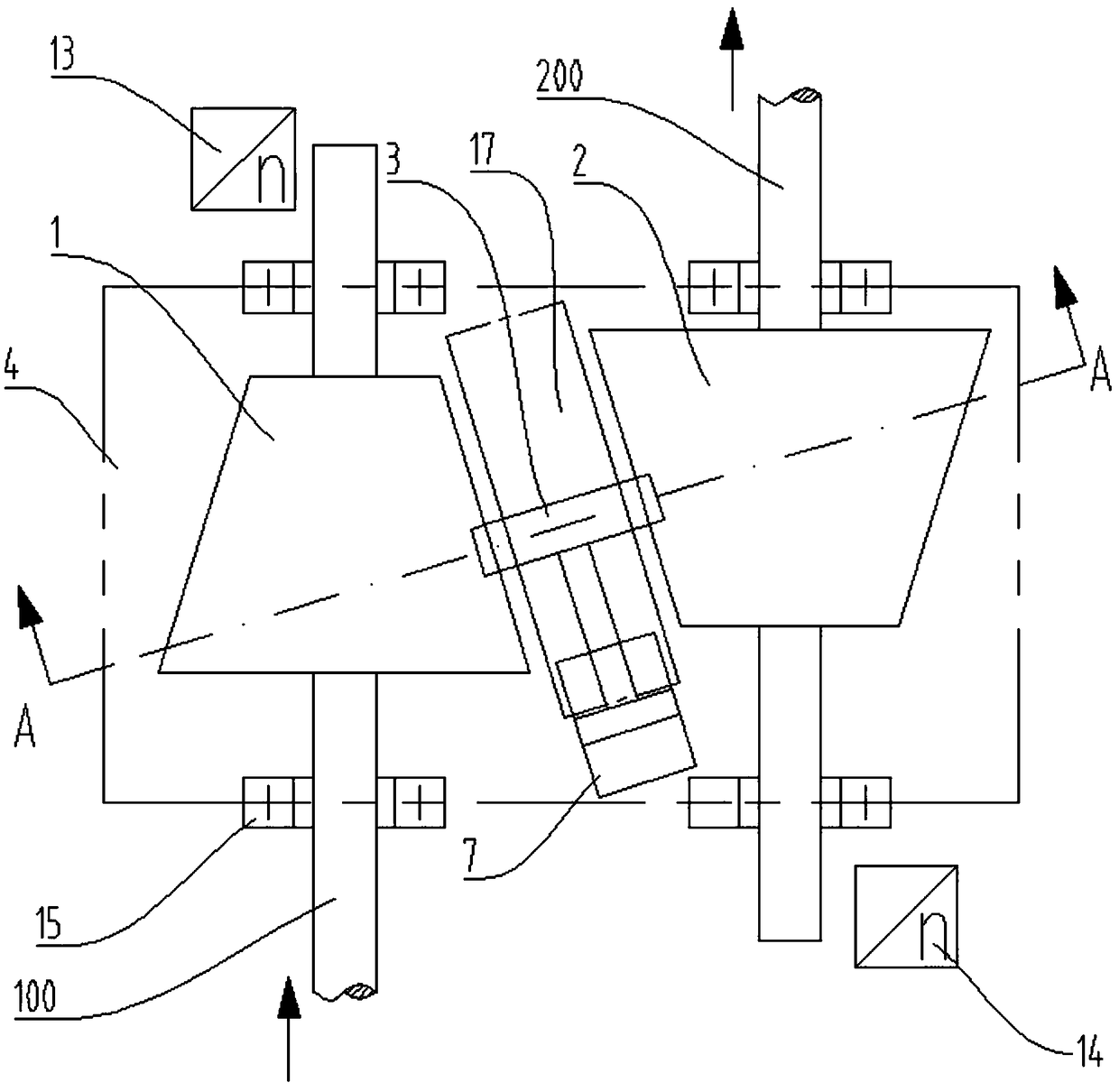
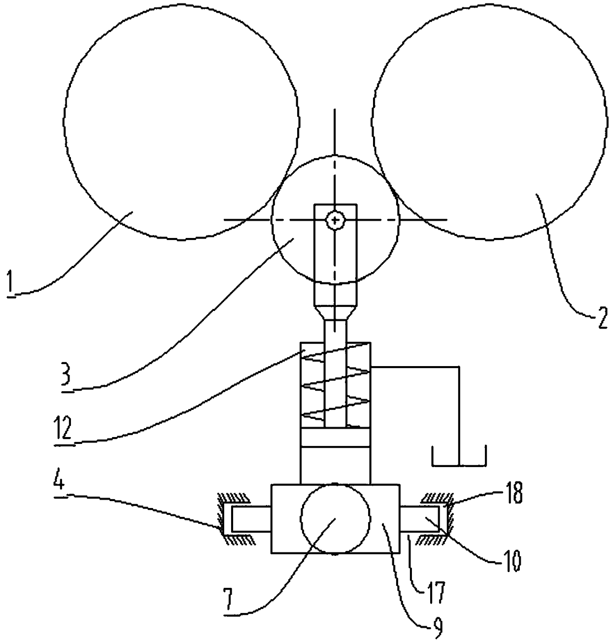
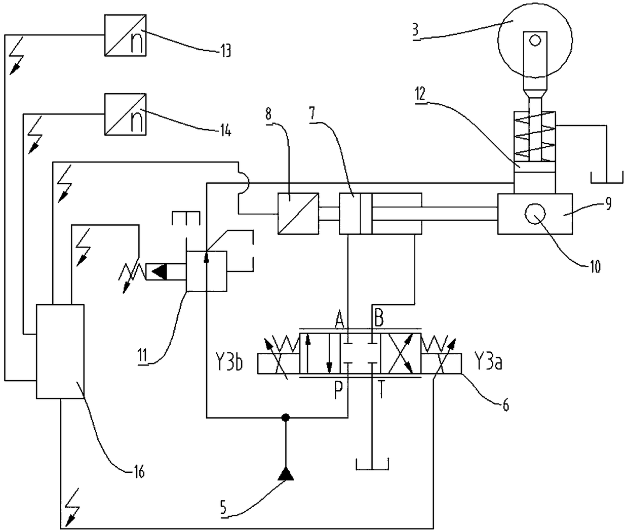
[0026] like Figure 1 to Figure 3 As shown, a frictionally driven continuously variable transmission device includes a casing 4, a driving shaft 100, a driven shaft 200, an intermediate wheel 3 arranged inside the casing 4, a second hydraulic cylinder 12 and a first hydraulic cylinder 7; The casing 4 is a box-type structure, which provides the installation basis for all components, and can also act as an oil tank for the hydraulic system. When the oil tank is full, an oil collecting cavity can be reserved at the bottom of the casing 4; the driving shaft 100 It is arranged in parallel with the driven shaft 200 and is respectively rotatably assembled on the left and right sides of the interior of the housing 4; the interior of the housing 4 is provided with mutually oppositely arranged and fixedly sleeved on the driving shaft 100 and the driven shaft 200 respectively. T...


PUM


Abstract

The invention relates to a friction transmission stepless speed change device. A driving shaft and a driven shaft are correspondingly and rotationally assembled on the left side and the right side ofthe inside of a shell. A first conical wheel arranged on the driving shaft in a sleeving manner and a second conical wheel arranged on the driven shaft in a sleeving manner are arranged opposite to each other. A slideway is arranged in a lower shell body of the shell, and a pair of sliding grooves is formed in both sides of the slideway. A foundation base is arranged in the middle of the slideway,and a pair of sliding blocks fixedly connected to both sides of the foundation base is slidably arranged in the pair of sliding grooves. A middle wheel is located between the first conical wheel andthe second conical wheel and is in friction fit with the conical surfaces of the first conical wheel and the second conical wheel at the same time. A base of the second hydraulic cylinder is fixedly connected with the foundation base, and the piston rod end of the second hydraulic cylinder is rotationally connected with the middle wheel. A first hydraulic cylinder is connected inside the shell. The piston rod end of the first hydraulic cylinder is fixedly connected with the center of the side end face of the foundation base. The combined device can conveniently and fast realize the stepless speed change adjustment of a transmission system and can conveniently and fast realize the compensation adjustment function under the condition of abrasion of a transmission wheel.

Description

technical field [0001] The invention belongs to the technical field of transmission, in particular to a continuously variable transmission device of friction transmission. Background technique [0002] Continuously variable transmission technology, using the transmission belt and the variable working diameter of the main and driven wheels to transmit power, can realize the continuous change of the transmission ratio, so as to obtain the best match between the transmission system and the engine working conditions. [0003] Common CVTs include hydromechanical CVT and metal belt CVT. There are many types of mechanical stepless speed change mechanisms, the main principle is to continuously change the working radius of the transmission wheel, which is easier to achieve with the use of cone wheels, and it is more convenient to use friction transmission between the cone wheels, so the friction transmission of the cone wheels becomes One of the most commonly used continuously varia...

Claims


Application Information

Patent Timeline
IPC IPC(8): F16H9/08F16H61/462
CPCF16H9/08F16H61/462
Inventor 李建松孙金海黎少辉张文婷
Owner XUZHOU COLLEGE OF INDAL TECH
Why Eureka
Try Eureka