A method for measuring and calibrating the missed distance of laser target projectiles based on pulse shadow imaging

A calibration method, a technology of missing target amount, applied in the direction of measuring device, mechanical gap measurement, using optical device, etc., can solve the problems of response consistency difference, projectile velocity error, projectile flight distance, etc., to achieve small size and high precision. , to ensure the effect of clear imaging

Active Publication Date: 2019-12-13
ZHONGBEI UNIV
View PDF8 Cites 0 Cited by
  • Summary
  • Abstract
  • Description
  • Claims
  • Application Information

AI Technical Summary

Problems solved by technology

In addition, due to the difference in the response consistency of the timing of the pulses generated by the projectile passing through the start target and the stop target, the position of the timing timing of the pulse generated by the projectile passing through the light curtain is inconsistent with the actual position of the light curtain, which will cause the projectile to fly within the interval of the timing timing. The distance is not equal to the actual target distance, so there is a certain error in the measured projectile velocity

Method used


Image

  • A method for measuring and calibrating the missed distance of laser target projectiles based on pulse shadow imaging
  • A method for measuring and calibrating the missed distance of laser target projectiles based on pulse shadow imaging
  • A method for measuring and calibrating the missed distance of laser target projectiles based on pulse shadow imaging

Examples


Embodiment Construction

[0025] The present invention will be described in detail below with reference to the accompanying drawings and examples.

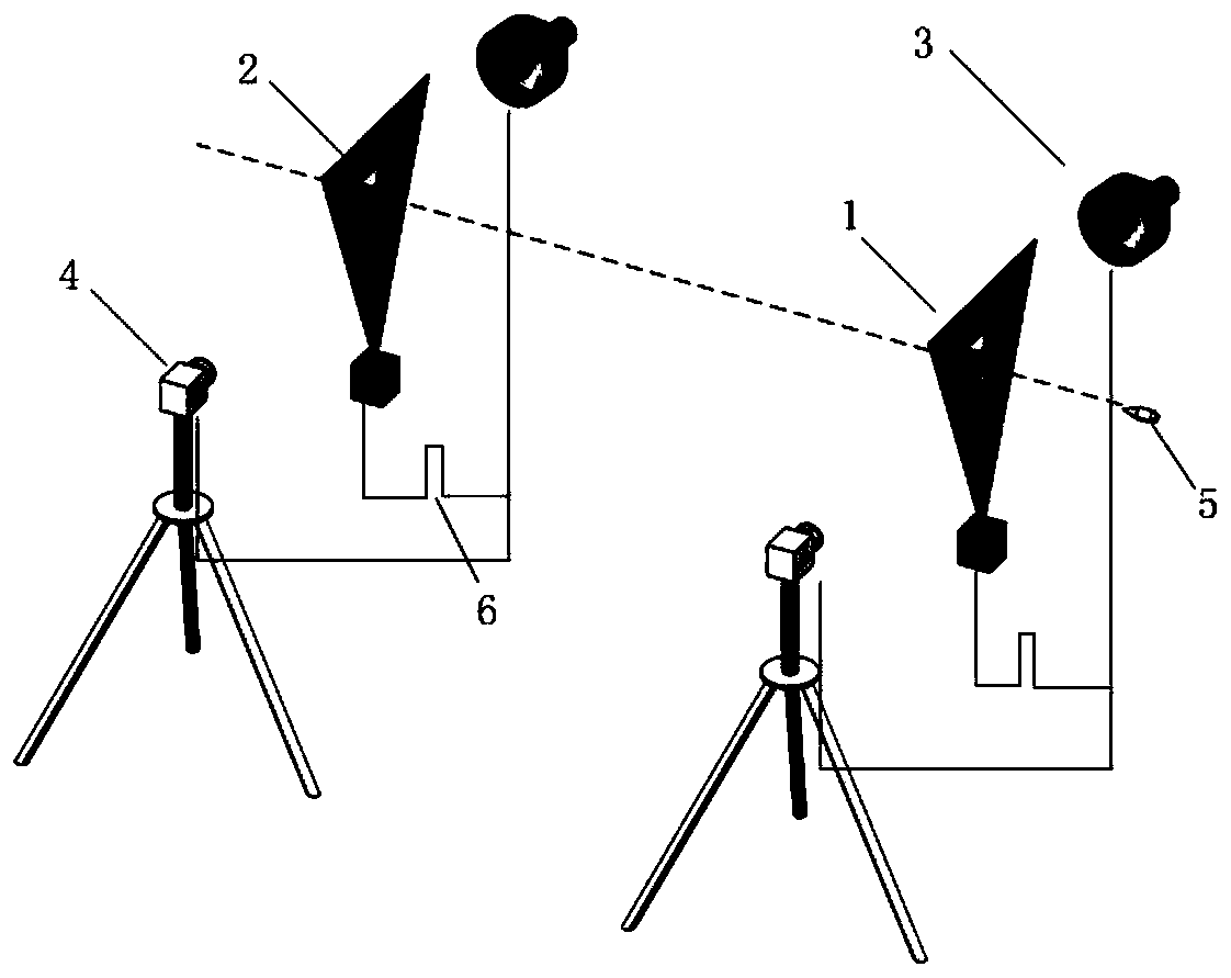
[0026] A method for measuring and calibrating the amount of laser target projectiles missing the target based on pulse shadow imaging of the present invention is realized by using the start target subsystem and the stop target subsystem built, such as figure 1 As shown, both subsystems include four key parts: laser target 1, glass linear scale 2, pulsed parallel light source 3, and high-resolution camera 4.

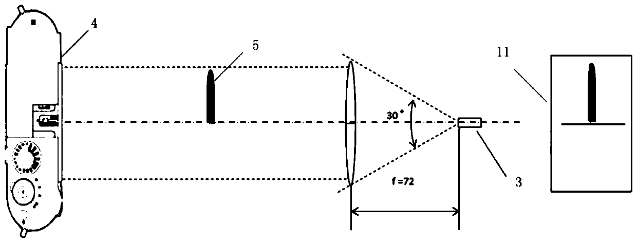
[0027] A pulsed parallel light source 3 and a high-resolution camera 4 are respectively set up on both sides of the laser light curtain of the laser target 1; as shown in FIG. format, forming bright areas on the image sensor.

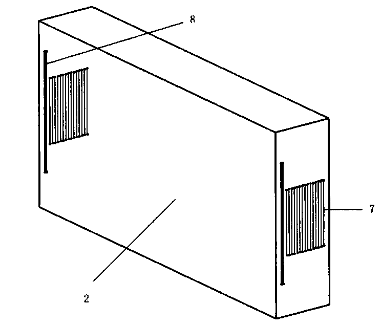
[0028] Such as image 3 As shown, the glass line ruler 2 is a rectangular parallelepiped glass block, and light curtain marking lines 8 and accurate reticle scales 7 are arranged on symmetrical positions on two opposite sides...


PUM


Abstract

The invention provides a pulse shadow imaging based laser target projectile miss distance measurement and calibration method. A special glass line ruler is arranged in a laser light screen, the special glass line ruler being used for calibrating the position of the laser light screen; pulse parallel light source illuminating cameras can be simultaneously adopted in a starting target and a stoppingtarget; shadow imaging can be performed on a marker line which is on a projectile and the glass line ruler and used for calibrating the position of the laser light screen; pixel sizes can be calibrated by using measured ruling span on the glass line ruler; and the distance between a projectile tail and the marker line (namely the laser light screen) can be measured, and therefore, the miss distance of projectiles can be accurately measured, and traceability calibration of miss distance measurement values can be realized. Compared with foreground lighting, the method adopts a mode of backlightshadow imaging so that the needed energy of pulse light sources is small, low demands on the materials and flying attitude of the projectiles can be achieved, and the capture rates of the projectilescan be enhanced.

Description

technical field [0001] The invention belongs to the technical field of photoelectric detection, and in particular relates to a method for measuring and calibrating the missing amount of laser target projectiles based on pulse shadow imaging. Background technique [0002] Projectile speed is an important indicator to measure the performance of weapons. The laser light curtain speed measurement system (laser target for short) is often used in shooting range projectiles because of its high precision, fast response speed, high sensitivity, strong anti-interference ability, and non-contact measurement. A high-precision test of speed and a calibration device for speed measuring equipment. The laser target adopts the section test method, that is, by testing the pulse time interval generated by the projectile passing through the two light curtains, and then calculating the projectile velocity from the measured target distance. Because the signal of the projectile passing the target...

Claims


Application Information

Patent Timeline
Patent Type & Authority Patents(China)
IPC IPC(8): G01B11/14G01B5/14
CPCG01B5/14G01B11/14
Inventor 赵冬娥张斌周汉昌赵辉李沅
Owner ZHONGBEI UNIV
Why Eureka
Try Eureka