
Flat-topped optical filter

An optical filter and optical filtering technology, applied in the field of optical filters, can solve the problems of complex devices, uncoordinated, poor working stability, etc., and achieve the effect of miniaturization, simple structure, and coordinated flat-top filtering.

Pending Publication Date: 2018-10-26
O NET COMM (SHENZHEN) LTD
View PDF0 Cites 1 Cited by
  • Summary
  • Abstract
  • Description
  • Claims
  • Application Information

AI Technical Summary

Problems solved by technology

[0010] The technical problem to be solved by the present invention is to provide a flat-top optical filter for the above-mentioned defects of the prior art, which overcomes the defects of incompatibility, complicated devices and poor working stability

Method used


Image

  • Flat-topped optical filter
  • Flat-topped optical filter
  • Flat-topped optical filter

Examples


Embodiment Construction

[0030] Now in conjunction with the accompanying drawings, the preferred embodiments of the present invention will be described in detail.

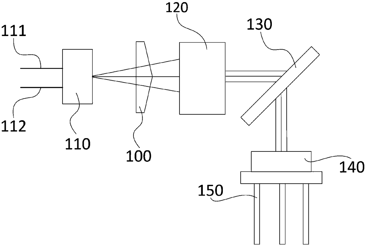
[0031] Such as figure 1 As shown, the present invention provides a preferred embodiment of the flat-top optical filter.

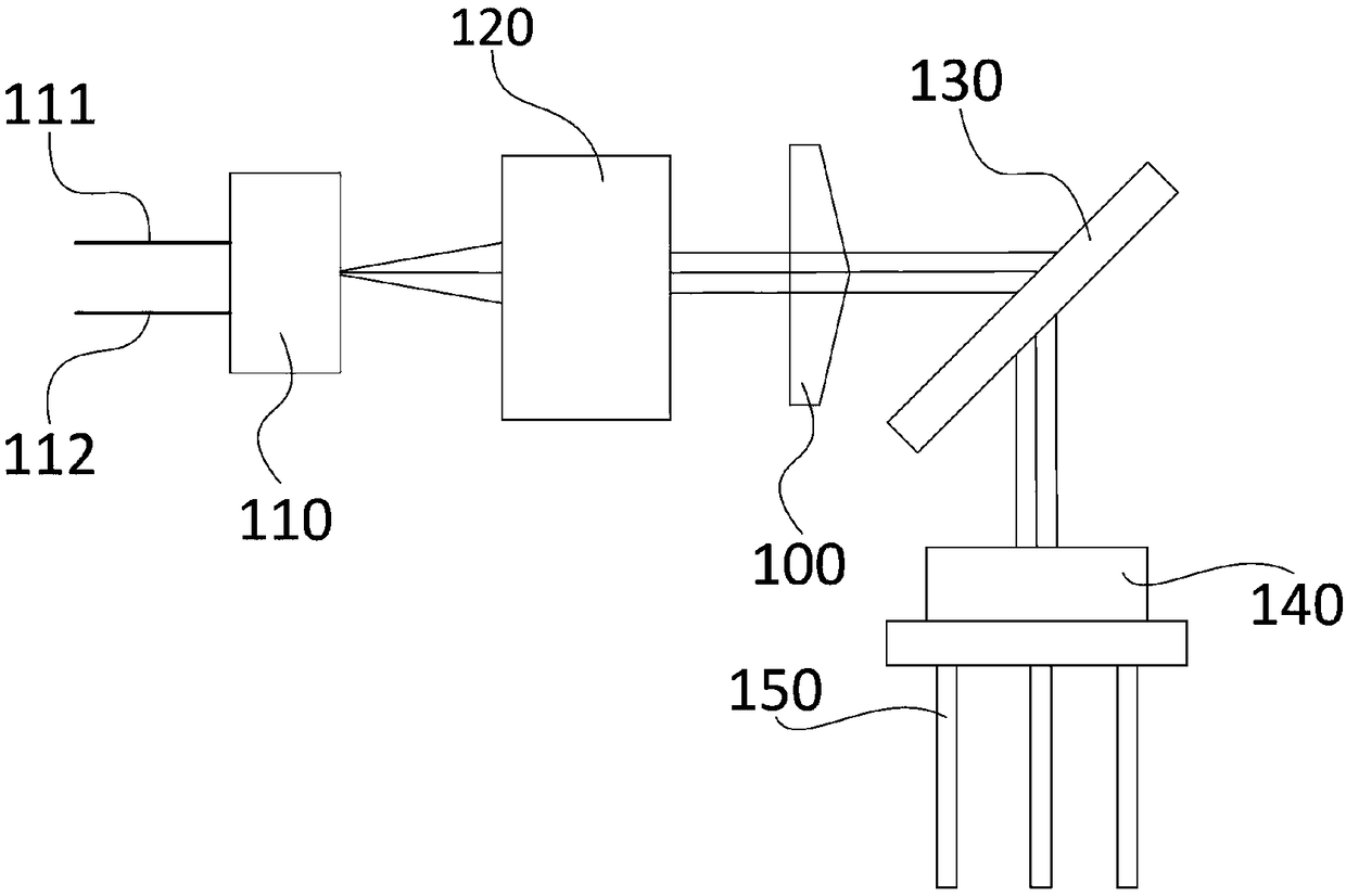
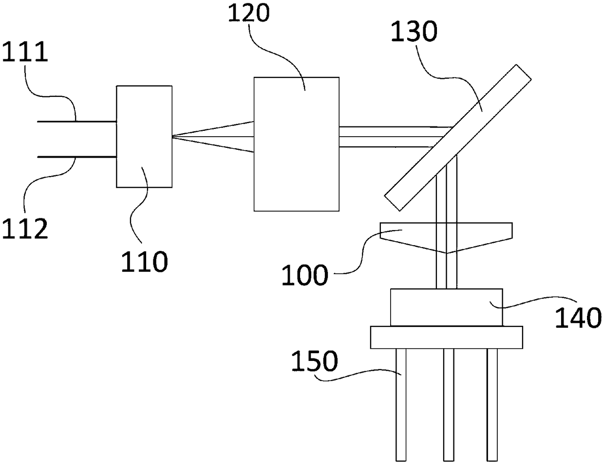
[0032] A flat-top optical filter, the optical filter includes an optical fiber input end 111 and an optical fiber output end 112, and an optical filtering path arranged between the optical fiber input end 111 and the optical fiber output end 112, the optical filtering path Comprising a collimating lens 120, a transmission grating 130 and a wavelength tuning module, the optical filter also includes an optical variable lens 100 arranged in the optical filtering path, and the optical variable optical lens 100 includes two intersecting plane mirrors, two of which The plane mirror is arranged symmetrically along the center line of the optical filtering path.

[0033] Specifically, two better solutions are provided,

[003...


PUM


Abstract

The invention relates to the field of optical filters, in particular to a flat-topped optical filter which comprises an optical fiber input terminal, an optical fiber output terminal, an optical fiberpath, an optical variability lens and a shell, wherein the optical fiber path is arranged between the optical fiber input terminal and the optical fiber output terminal, and the optical variability lens is arranged in the optical fiber path. The optical fiber path comprises an alignment lens, an optical grating and a wavelength tuning module, an optical path is divided into two paths by the optical variability lens to form two Gaussian beams with different central wavelengths, the two Gaussian beams are overlaid by a processing module to form a flat-topped beam, the alignment lens, a transmission grating, the wavelength tuning module and the optical variability lens are arranged in a cavity of the shell, a tunable flat-topped filter wave is achieved, and the optical filter is simple in structure and small in size.

Description

technical field [0001] The invention relates to the field of optical filters, in particular to a flat-top optical filter. Background technique [0002] An optical filter is an instrument used for wavelength selection. It can select the desired wavelength from many wavelengths, and light other than this wavelength will be rejected. [0003] In modern intelligent optical communication network, tunable optical filter is an indispensable device, and flat top and miniaturization are its development trend. From the working principle, there are mainly four schemes to realize optical filtering in optical fiber communication network, which are based on fiber Bragg grating structure, thin-film filter, Fabry-Perot resonator and tunable filter based on free space optical structure. [0004] However, there are defects in the above-mentioned schemes, specifically: [0005] 1. The optical filter based on the fiber Bragg grating structure can realize an all-fiber structure and a flat top,...

Claims


Application Information

Patent Timeline
Patent Type & Authority Applications(China)
IPC IPC(8): G02B26/00G02B27/10
CPCG02B26/00G02B27/10
Inventor 徐颖鑫张江涛金顺平徐炜谢红
Owner O NET COMM (SHENZHEN) LTD
Learn More