
Mechanical automatic tracking winding displacement device

A technology of automatic tracking and cable arrangement, applied in coil manufacturing, inductor/transformer/magnet manufacturing, electrical components, etc., can solve the problems of complex equipment design, relatively high cost, time-consuming and labor-intensive, etc., and achieve simple structure and low cost , the effect of reducing production costs

Active Publication Date: 2018-10-26
敬德强
View PDF5 Cites 2 Cited by
  • Summary
  • Abstract
  • Description
  • Claims
  • Application Information

AI Technical Summary

Problems solved by technology

When taking up and winding the wires, manual wiring can make the winding and winding neat, but it is time-consuming and laborious, and the efficiency is extremely low. It can be used in a single case in the maintenance field.
[0003] At present, a large number of applications are automatic cable arrangement equipment. The current automatic cable arrangement equipment is composed of a mechanical cable arrangement device, a drive control system and a winding device. The design of the equipment is complicated and the relative cost is relatively high.

Method used


Image

  • Mechanical automatic tracking winding displacement device
  • Mechanical automatic tracking winding displacement device
  • Mechanical automatic tracking winding displacement device

Examples


Embodiment

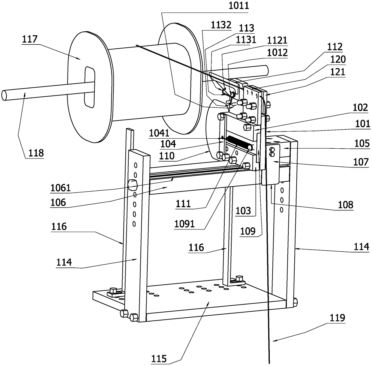
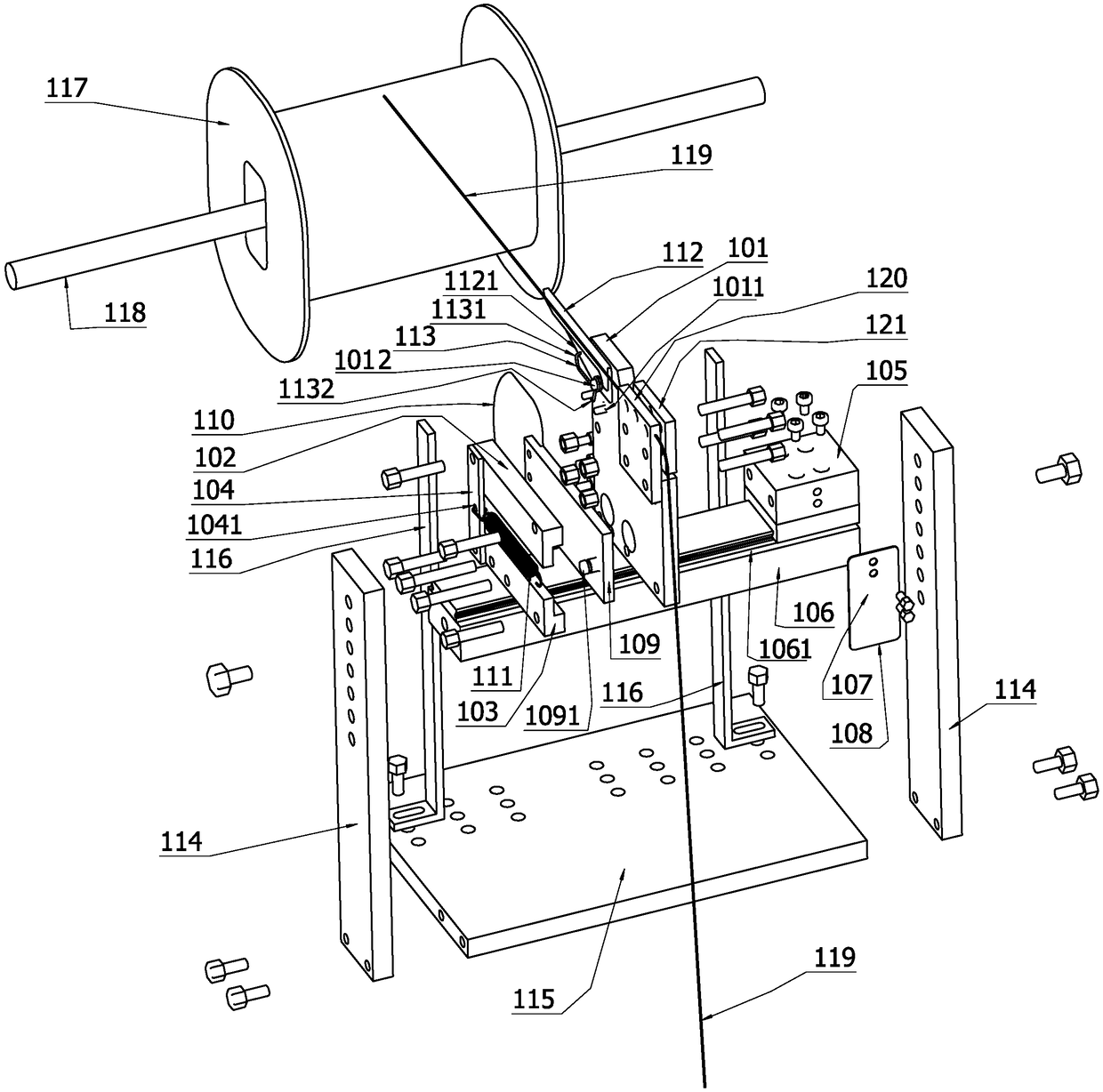
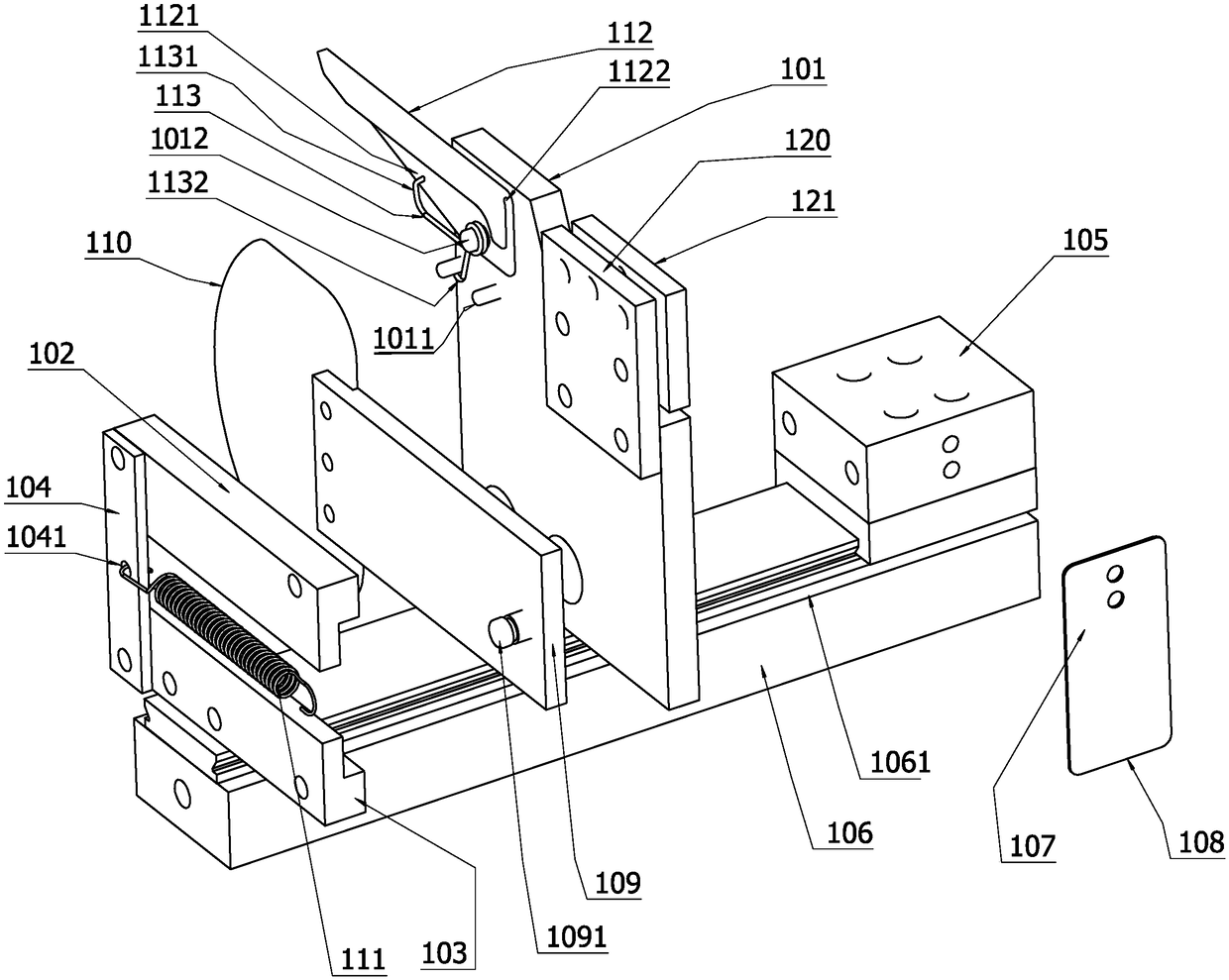
[0012] Example: such as Figure 1-Figure 4 As shown, in this embodiment, the present invention includes a frame, a slide rail, a slider, a base plate, a depressing tongue, a piston, a piston seat, a probing tongue, a torsion spring, a spring, a wire damping device, a limit rod, etc. . The frame consists of the lower base plate (115), the left and right columns (114) and the upper beam (106) fixed into a square frame by screws, the lower base plate (115) can be combined with the fixed winding machine, etc.; The screw is installed and fixed with a slide rail (1061) along the direction of the upper beam, and a slide block (105) is installed on the slide rail (1061), and the slide block (105) can freely move left and right along the slide rail (1061) direction on the slide rail (1061). Sliding; the vertical surface of the slide rail (1061) of the slide block (105) is fixed with a base plate (101) by screws, and the upper and lower piston seats (102, 103), the upper and lower pis...


PUM


Abstract

The invention provides a mechanical automatic tracking winding displacement device. The mechanical automatic tracking winding displacement device comprises a frame, a slide rail, a slide block, a baseplate, a pressing tongue, a piston, piston seats, a detection tongue, a torsional spring, a spring, a linear damping device, limiting rods and the like, wherein the frame is a square frame consistingof a lower bottom plate, stand columns and an upper cross beam; the slide rail is arranged on the upper cross beam; the slide block is arranged on the slide rail; the base plate is arranged on a slide rail vertical plane of the slide block; the piston seats and the piston are arranged on a lower part of the base plate; the detection tongue is arranged at one end of the piston; a spring buckle isarranged at the other end of the piston; a spring clamping plate at one end of each piston seat close to the detection tongue is connected with one end of a tension spring; the other end of the tension spring is connected with the spring buckle; the pressing tongue is arranged on an upper part of the base plate close to a detection tongue end; the pressing tongue is arranged on the base plate through a fixing pin; the torsional spring is arranged on the pin; one end of the torsional spring is clamped on the base plate; the other end of the torsional spring is clamped on a lower part of the pressing tongue; linear dampers are arranged on the upper part of the base plate close to an end opposite to the pressing tongue; left and right limiting rods are arranged on the lower bottom plate of the frame along the slide rail; a side face of the slide block is provided with a damping elastic sheet along a direction parallel to the slide rail; and a wear-resistant damping material is arranged onthe damping elastic sheet close to a cross beam side.

Description

technical field [0001] The invention relates to the field of various wire winding and wire arranging devices, in particular to a mechanical automatic tracking winding and arranging device. Background technique [0002] At present, wire winding and winding equipment are widely used in various industrial production, equipment maintenance and other fields. In order to ensure neat winding and winding, wire arranging equipment is an essential part. When taking up and winding the wires, manual wiring can achieve tidy winding and winding, but it is time-consuming and laborious, and the efficiency is extremely low. It can be used in a single case in the maintenance field. [0003] At present, a large number of applications are automatic cable arrangement equipment. The current automatic cable arrangement equipment is composed of a mechanical cable arrangement device, a drive control system and a winding device. The design of the equipment is relatively complicated and the relative c...

Claims


Application Information

Patent Timeline
Patent Type & Authority Applications(China)
IPC IPC(8): H01F41/06H01F41/082H01F41/08
CPCH01F41/06H01F41/08H01F41/082
Inventor 敬德强
Owner 敬德强
Learn More