
Quantum key distribution system and method

A quantum key distribution and key technology, applied in the field of quantum information, can solve the problems of low key rate and high transmitter cost, and achieve the effect of improving key rate and reducing equipment cost

Active Publication Date: 2018-10-26
TSINGHUA UNIV
View PDF11 Cites 4 Cited by
  • Summary
  • Abstract
  • Description
  • Claims
  • Application Information

AI Technical Summary

Problems solved by technology

Therefore, it can be seen that in the above two methods in the prior art, since four kinds of quantum states are used, the cost of the transmitter is relatively high, and the final key rate of the system is relatively low.

Method used


Image

  • Quantum key distribution system and method
  • Quantum key distribution system and method
  • Quantum key distribution system and method

Examples


specific Embodiment 1

[0077] Specific embodiment 1: Only one laser is provided in the transmitting device.

[0078] For example, preferably, in the specific embodiment of the present invention, image 3 It is a schematic structural diagram of the quantum key distribution system in the first embodiment of the present invention, such as image 3 As shown, the sending device 21 includes: a first controller 211, a laser 212, and a modulator 213; the receiving device 22 includes: a single photon detection unit 221 and a second controller 222;

[0079] The signal output end of the first controller 211 is connected to the laser 212 and the modulator 213; the output end of the laser 212 is connected to the modulator 213; the output end of the modulator 213 is connected to the single photon detection unit through the transmission channel 23 221 is connected; the output end of the single photon detection unit 221 is connected to the second controller 222; the synchronization signal end of the first controller 211 ...

specific Embodiment 2

[0087] Specific embodiment 2: Two lasers are provided in the transmitting device.

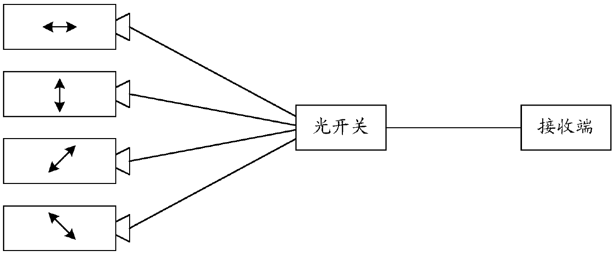
[0088] For example, preferably, in the specific embodiment of the present invention, Figure 4 It is a schematic diagram of the structure of the quantum key distribution system in the second embodiment of the present invention, such as Figure 4 As shown, the transmitting device 21 includes a first controller 41, a first laser 42, a second laser 43, and a modulator 44; the receiving device 21 includes a single photon detection unit 221 and a second controller 222;

[0089] The signal output ends of the first controller 41 are respectively connected to the first laser 42, the second laser 43, and the modulator 44; the output ends of the first laser 42 and the second laser 43 are both connected to the modulator 44; The output end of the modulator 44 is connected to the single photon detection unit 221 through the transmission channel 23; the output end of the single photon detection unit 221 is connect...


PUM


Abstract

The invention provides a quantum key distribution system and method. The system comprises a sending device and a receiving device. The sending device is used for randomly sending two predetermined nonorthogonal quantum states |phi> and |Phi> to the receiving device and discarding data of which a measurement result is null and which corresponds to |phi> or |Phi>. The receiving device is used for measuring the received quantum states by random use of one of two groups of measurement bases to obtain measurement results, sending information of data positions corresponding to a non-null measurementresult, |phi> and |Phi> to the sending device and discarding the data of which the measurement result is null and which corresponds to |phi> or |Phi>. Each of the sending device and the receiving device is used for performing parameter estimation according to left data of a preset part to obtain a bit error rate and, when the bit error rate is not higher than a preset threshold, performing errorcorrection and privacy amplification to obtain a key. According to the quantum key distribution system and method, secure quantum key distribution can be implemented by use of only two nonorthogonal quantum states, so that the equipment cost is reduced and the key rate is increased.

Description

Technical field [0001] This application relates to the field of quantum information technology, in particular to a quantum key distribution system and method. Background technique [0002] With the rapid development of Internet technology, the importance of communication security is increasing day by day. In many situations, both parties in communication hope to conduct confidential communication while using public channels. For example, when a user submits an account number and password to online banking, the user hopes that this information will be kept confidential during the transmission process, that is, no third party can eavesdrop. The currently widely used encryption method is the public key encryption algorithm. Such algorithms are based on the algorithmic complexity of certain mathematical problems. With the development of technology, their security is threatened. Therefore, we urgently need to develop more secure and reliable encryption methods. [0003] Quantum key ...

Claims


Application Information

Patent Timeline
Patent Type & Authority Applications(China)
IPC IPC(8): H04L9/08
CPCH04L9/0858
Inventor 马雄峰马家骏
Owner TSINGHUA UNIV
Learn More