Electronic part bending mechanism

A technology of bending mechanism and electronic parts, which is applied in the field of bending mechanism of electronic parts, can solve the problems of inaccurate control of the angle of bending feet, hidden dangers of quality, low efficiency, etc., so as to ensure the uniformity and stability of bending, and the bending speed And the effect of uniform strength and saving waiting waste

Inactive Publication Date: 2018-10-30
BOZHON PRECISION IND TECH CO LTD
View PDF5 Cites 5 Cited by
  • Summary
  • Abstract
  • Description
  • Claims
  • Application Information

AI Technical Summary

Problems solved by technology

[0002] With the wide application of electronic components and electronic integrated circuits, the use and installation of traditional electronic components are to use the bare wire pins at both ends of the components to be directly inserted into the mounting holes of the printed circuit board and then soldered, while the component pins need to be lengthened and The use and installation occasions that need to be insulated are all manually operated. Manually fold the pins of each component pin first, the

Method used


Image

  • Electronic part bending mechanism
  • Electronic part bending mechanism
  • Electronic part bending mechanism

Examples


Embodiment Construction

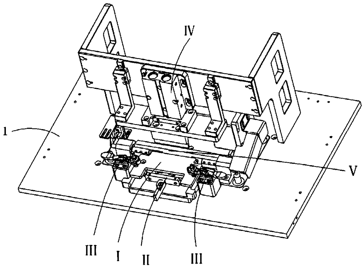
[0031] Examples, see attached Figure 1-10 , a bending mechanism for electronic parts, comprising a bottom plate 1, a carrier mechanism I is placed on the bottom plate, and a plurality of groups of electronic components 2 are arranged side by side in the carrier mechanism, the front ends of the electronic components are cylindrical structures, and the electronic components There are two pins 3 that need to be bent at the rear end of the component.

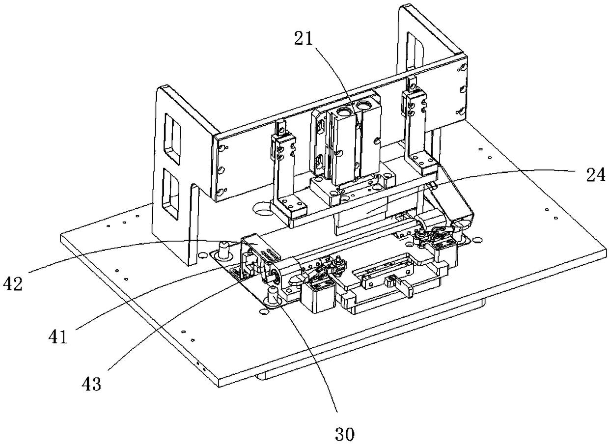
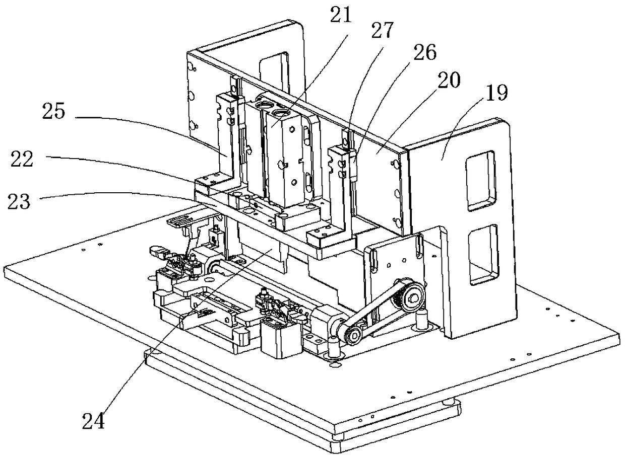
[0032] The carrier mechanism includes a carrier plate 4, and the carrier plate is provided with multiple sets of product placement slots 5, and electronic components 2 are placed in the product placement slots; the carrier plate is provided with a product limiting position behind the electronic components Device II, the carrier board is provided with a convex groove 6 at the position of the product limiting device, and the product limiting device includes a limiting fixed plate 7 fixed on the carrier plate by screws and a limiting ...


PUM


Abstract

The invention relates to an electronic part bending mechanism. A carrier is placed on a base plate, a plurality of electronic components are installed in the carrier side by side, two pins which needto be bent are arranged on each electronic component, and tight press mechanisms which can tightly press the carrier and products are installed on the base plate and located on the left side and the right side of the carrier. A downward press mechanism which can press the pins is installed on the rear side of the top of the base plate. A square slotted hole is formed in the middle of the base plate, an ascending mechanism is installed at the bottom of the base plate, and an ascending plate of the ascending mechanism can pass through the square slotted hole. An upper bending mechanism is installed on the ascending plate, and comprises a rotating mechanism and a bending driving device, wherein the bending driving device can drive a rotating shaft of the rotating mechanism to rotate. An upperbending block which can conduct bending forming on the pins is installed on the rotating shaft. A sensor which can control the rotation angle of the rotating shaft is installed on the ascending plate, and an induction piece which is matched with the sensor is installed on the rotating shaft. By the adoption of the electronic part bending mechanism, bending operation of the electronic components can be achieved, the multiple products can be bent at one time, and the operation of bending with different angles can be achieved.

Description

Technical field: [0001] The invention relates to the field of bending equipment, and more specifically relates to a bending mechanism for electronic parts. Background technique: [0002] With the wide application of electronic components and electronic integrated circuits, the use and installation of traditional electronic components are to use the bare wire pins at both ends of the components to be directly inserted into the mounting holes of the printed circuit board and then soldered, while the component pins need to be lengthened and The use and installation occasions that need to be insulated are all manually operated. Manually fold the pins of each component pin first, then bend the pins into a hook shape, and then cut off the excess part of the pins, and then cut off the pins on each resistor. Welding with insulating pins, and the operation process is affected by human factors, there are certain quality hazards and risks in the process of bending the feet, and the ang...

Claims


Application Information

Patent Timeline
IPC IPC(8): B21F1/00
CPCB21F1/00
Inventor 王建福杨洋
Owner BOZHON PRECISION IND TECH CO LTD
Why Eureka
Try Eureka