Rubberizing device and rubberizing method thereof, cylindrical battery cell flaking winding machine

A glue sticking device and sticking technology, which is applied in the direction of cylindrical shell battery/battery, secondary battery manufacturing, circuit, etc., can solve the problem that the cell is easily compacted too tightly, which affects the overall time of sticking and affects the quality of the cell. and other problems, to achieve the effect of ensuring the quality of the glue, preventing the compaction from being too tight, and ensuring the quality of the winding

Active Publication Date: 2018-10-30
ZHUHAI HIGRAND ELECTRONICS TECH
View PDF6 Cites 3 Cited by
  • Summary
  • Abstract
  • Description
  • Claims
  • Application Information

AI Technical Summary

Problems solved by technology

However, the existing gluing device has the disadvantage of low production efficiency, because the existing gluing device first sticks the first end of the tape on the rolled battery when the battery is glued. The outer peripheral surface, and then the tape is wound on the outer peripheral surface of the cell through the rotation of the winding needle, and then the tape is cut and finished after winding to an appropriate length, so that the cutting of the tape nee

Method used


Image

  • Rubberizing device and rubberizing method thereof, cylindrical battery cell flaking winding machine
  • Rubberizing device and rubberizing method thereof, cylindrical battery cell flaking winding machine
  • Rubberizing device and rubberizing method thereof, cylindrical battery cell flaking winding machine

Examples


Embodiment Construction

[0032] Cylindrical cell sheet winding machine embodiment:

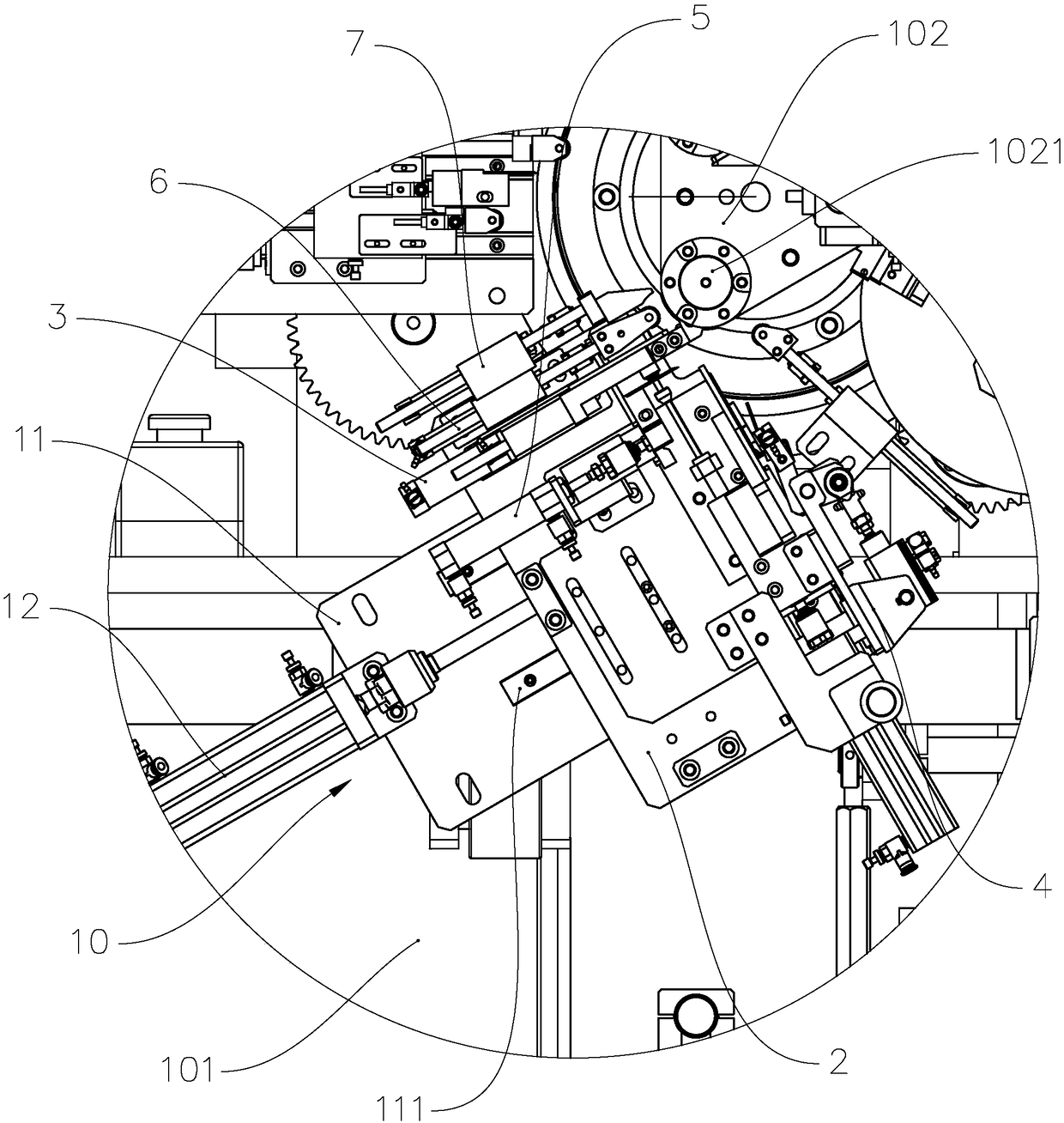
[0033] refer to figure 1 , the cylindrical battery sheet winding machine includes a frame 101, a winding head 102 and a glue application device 103, wherein the winding head 102 is rotatably mounted on the frame 101 around its own axis, and the winding head 102 is used for After the positive pole piece, negative pole piece, separator, etc. are wound into batteries at the winding station, the rolled battery cores are moved to the gluing station for gluing the rolled battery cores. The gluing device 10 is installed on the frame 101, and the gluing device 10 is positioned at the gluing station of the winding head 102, and the gluing device 101 is used for winding the electric coils rolled by the winding head 102 at the winding station. The core is glued to prevent the rolled battery core from falling apart.

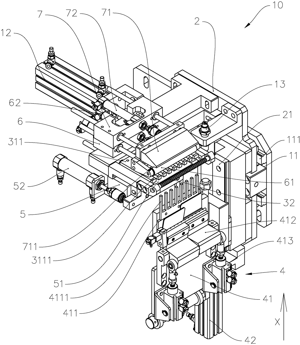
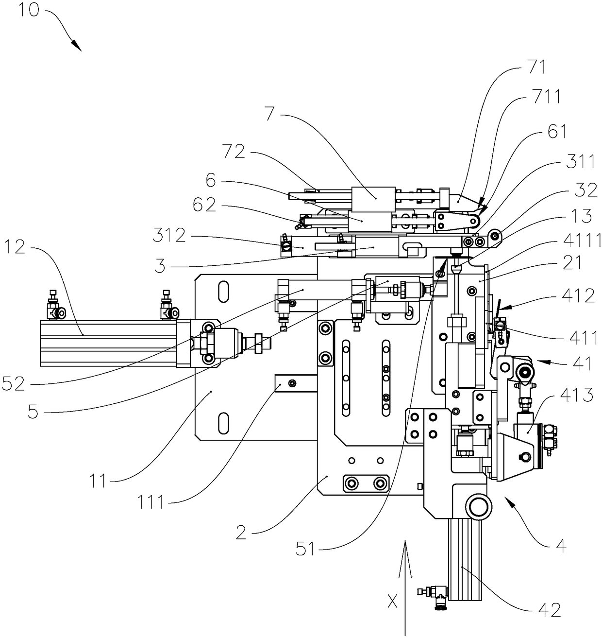
[0034] refer to figure 2 and image 3 , and combined with figure 1 The gluing device 10 includes a mounting...


PUM


Abstract

The invention provides a rubberizing device and a rubberizing method thereof, a cylindrical battery cell flaking winding machine, and the rubberizing device comprises a connecting base which is provided with a first guide rail, a glue supplying unit, and a glue preparation unit, a cutting blade unit and a rubberizing unit which are all mounted on the connection base, wherein the glue preparation unit comprises a glue preparation roller and a glue pressing mechanism of which an output end moves in the manner of being opposite to or back to the glue preparation roller; the glue supplying unit comprises a glue supplying mechanism connected with the first guide rail in the manner of sliding, and a first driving mechanism connected between the connecting base and the glue supplying mechanism; the glue supplying mechanism can move along the first guide rail to a space between the glue pressing mechanism and the glue preparation roller; and the cutting blade unit comprises a cutting blade mounted on the connecting base in the manner of sliding, and the cutting blade unit, the glue preparation unit and the rubberizing unit are orderly arranged along a feeding direction of the glue supplying unit. The rubberizing method of the rubberizing device and the cylindrical battery cell flaking winding machine are also provided, and the rubberizing device, the rubberizing method of the rubberizing device and the cylindrical battery cell flaking winding machine all have the advantages of high production efficiency and can avoid that a battery cell is compacted too tightly in a rubberizing process.

Description

technical field [0001] The invention relates to the technical field of battery production, in particular to a gluing device, a gluing method for the gluing device, and a cylindrical cell sheet winding machine provided with the gluing device. Background technique [0002] Existing lithium battery cells are generally rolled by a winding process. Usually, the positive electrode sheet, negative electrode sheet, and separator are stacked in a certain order, and then wound with a certain length through the winding needle of the winding head. And after the winding is completed, the rolled battery cores are bound with adhesive tape to prevent the rolled battery cores from loosening again. [0003] However, the current way to glue the rolled batteries is to stick a layer of tape along the rolling direction of the batteries (that is, the circumferential direction of the batteries) to fix the ends of the positive electrode, negative electrode, and diaphragm. , to prevent the rolled ba...

Claims


Application Information

Patent Timeline
IPC IPC(8): H01M10/0587H01M10/04H01M6/14
CPCH01M6/14H01M10/0422H01M10/0587Y02E60/10Y02P70/50
Inventor 杨琪吕海军曹海霞刘秀娟
Owner ZHUHAI HIGRAND ELECTRONICS TECH
Why Eureka
Try Eureka