Novel tracheal fistula orificium stent
A fistula and trachea technology, applied in the field of new tracheal fistula stents, can solve problems such as inconvenient drug treatment at the fistula, threat to the life of the patient, unfavorable closure of the fistula, etc., to prevent downward leakage and bacterial diffusion , to avoid bacterial infection, to enhance the effect of the effect
- Summary
- Abstract
- Description
- Claims
- Application Information
AI Technical Summary
Problems solved by technology
Method used
Image
Examples
Embodiment 1
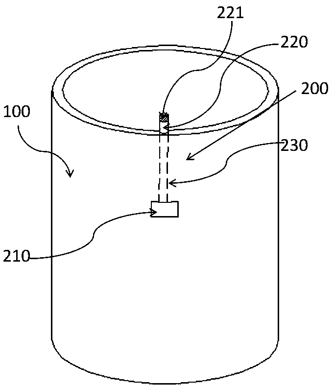
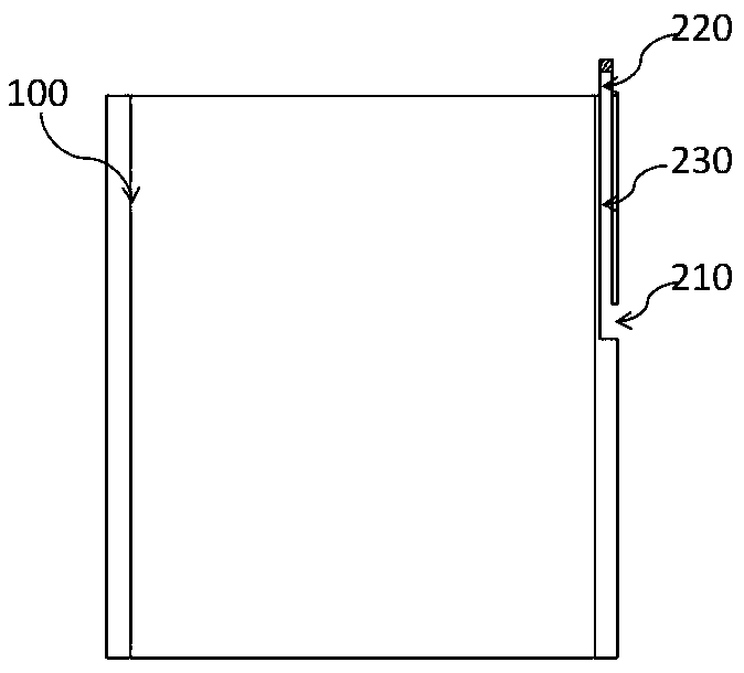
[0035] Such as Figure 1~2 As shown, a novel tracheal fistula stent includes a stent main body 100 that can be placed at the tracheal fistula in the human body, and a fistula communication mechanism 200 .
[0036] The fistula communication mechanism includes a notch 210 provided on the outer wall of the stent main body, a first joint 220 that can be used to connect an extracorporeal medical connection tube, and a connecting pipe 230 that is used to communicate the notch 210 and the first joint 220 . Such as figure 1 As shown, the first joint 220 is disposed on the edge of the side wall at the upper end of the bracket body 100 . The first connector 220 adopts a heparin lock structure similar to the medical infusion field.
[0037] The notch 210 may not penetrate the side wall, or may penetrate the side wall. In this embodiment, the notch 210 is arranged at the outer side wall of the bracket body 100, the connecting pipe 230 is arranged in the side wall of the bracket body 10...
Embodiment 2
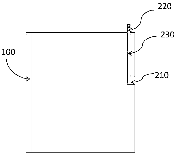
[0040] This embodiment is the second embodiment of the present invention, and the difference from Embodiment 1 lies in the arrangement of the notch, specifically, as image 3 As shown, the notch 210 runs through the outer wall and the inner wall of the bracket body 100, the connecting pipe 230 is installed on the inner wall of the bracket body 100, one end of the connecting pipe 230 is airtightly connected with the notch 210, and the other end of the connecting pipe 230 is connected with the first Connector 220 is connected. The connecting pipe 230 has an oblate structure, and the part of the connecting pipe 230 in contact with the inner wall of the bracket main body 100 is integrally formed with the inner wall of the bracket main body 100. Through such arrangement, the volume occupied by the connecting pipe can be reduced as much as possible.
[0041] Other components and connection relations are the same as in Embodiment 1.
Embodiment 3
[0043] This embodiment is the third embodiment of the present invention, different from Embodiment 1 or 2, as Figure 5 and 6 As shown, the stent main body 100 in this embodiment is also provided with an airbag 300 for enhancing the stability of the stent main body 100 and a second joint 400 that can be connected with an inflatable tube outside the body. Same as the first joint, the second joint 400 is arranged on the edge of the side wall of the upper end of the bracket body, and the first joint 220 and the second joint 400 can be located on the same side or opposite to each other. The second joint 400 communicates with the inside of the airbag 300 to inflate the airbag 300 . Generally, in the inflated state, the thickness of the airbag is 3~4mm. The airbag 300 is a one-way valve airbag. Specifically, the airbag 300 is provided with an air intake one-way valve to ensure that the airbag 300 does not leak after being inflated.
[0044] The airbag 300 is disposed on the outer...
PUM
 Abstract
Description
Claims
Application Information
 - R&D
- Intellectual Property
- Life Sciences
- Materials
- Tech Scout
- Unparalleled Data Quality
- Higher Quality Content
- 60% Fewer Hallucinations
Browse by: Latest US Patents, China's latest patents, Technical Efficacy Thesaurus, Application Domain, Technology Topic, Popular Technical Reports.
© 2025 PatSnap. All rights reserved.Legal|Privacy policy|Modern Slavery Act Transparency Statement|Sitemap|About US| Contact US: help@patsnap.com


