Model plane

A model aircraft and model technology, applied in the field of model aircraft, can solve the problems of engine shedding, engine power loss, low design accuracy, etc., and achieve the effect of increasing output efficiency and reducing waste of resources

Pending Publication Date: 2018-11-02
JIANGYIN XIANGNUO ELECTRONICS TECH
View PDF13 Cites 2 Cited by
  • Summary
  • Abstract
  • Description
  • Claims
  • Application Information

AI Technical Summary

Problems solved by technology

[0002] Aircraft refers to a power plant with one or more engines to generate forward thrust or pull, and the fixed wings of the fuselage to generate lift. The aircraft is heavier than air and flies in the atmosphere. The aircraft is the most common type of fixed wing. Aircraft can be divided into jet planes and propeller planes according to the types of engines they use, and model planes are movable or static models that are installed with existing aircraft for special innovation. Model planes are generally the same as manned planes. Similarly, it is mainly composed of six parts: wing, empennage, fuselage, landing gear, engine and control system, and the engine is the most core part of the model aircraft. The existing aircraft models are low in cost and low in design accuracy, so When the engine is fixed, it will not use all-inclusive fixing, but only use a simple snap-fit ​​connection, but when the model aircraft does some stunts in flight, it will generate a large load inside the aircraft, and the engine itself will bear a large load. pressure, and simple fixation cannot meet the fixation under these special load conditions, which will lead to problems such as engine falling off. At the same time, most model aircraft use propellers to provide power, but the existing propellers basically use directional fixed propellers, and the engine cannot be The power of the engine is fully utilized. When taking off, the longitudinal propeller arrangement makes the power loss of the engine extremely serious.

Method used


Image

  • Model plane
  • Model plane
  • Model plane

Examples


Embodiment Construction

[0030] The technical solutions in the embodiments of the present invention will be clearly and completely described below in conjunction with the accompanying drawings in the embodiments of the present invention. Obviously, the described embodiments are only a part of the embodiments of the present invention, rather than all the embodiments. Based on the embodiments of the present invention, all other embodiments obtained by those of ordinary skill in the art without creative work shall fall within the protection scope of the present invention.

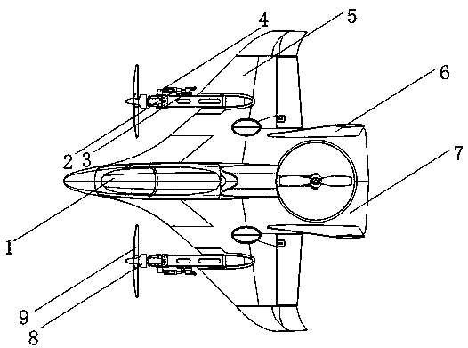
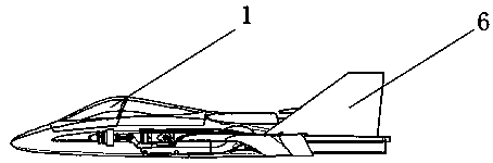
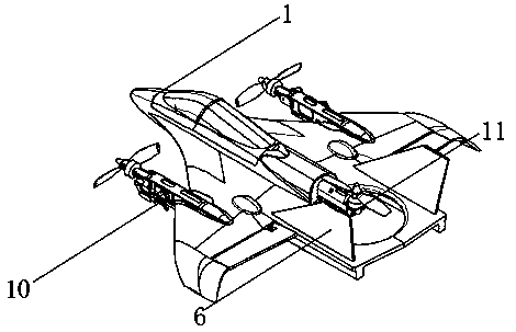
[0031] See Figure 1-6 , The present invention provides a technical solution: a model aircraft, including a model aircraft body 1, a model rear fuselage 7 is installed horizontally at the tail of the model aircraft body 1, and a model fixed tail 6 is installed vertically on both sides of the model rear fuselage 7 , The model main wing 5 is horizontally fixedly installed on both sides of the middle of the model aircraft body 1, the middle...


PUM


Abstract

The invention discloses a model plane which comprises a model plane body. A model rear plane body is mounted at the horizontal position of the tail of the model plane body, model fixed tail wings arevertically mounted on two sides of the model rear plane body, model main wings are horizontally and fixedly mounted on two sides of the middle of the model plane body, upper shells are embedded into the middles of the model main wings, a first motor steering engine is embedded into one side of each upper shell, a first crank is connected with one side of each first motor steering engine through apin, a second connecting rod is connected at the tail end of each first crank, a first connecting rod is movably connected at the tail end of each second connecting rod, a second crank is movably connected at the tail end of each first connecting rod, and a motor connector is arranged at the tail end of each second crank. According to the model plane, the falling off probability of an engine can be reduced, flight safety is improved, the plane is provided with a crank mechanism, a power output direction is changed, utilization of engine efficiency is improved, and power wastage is reduced.

Description

Technical field [0001] The invention relates to the field of airplane models, in particular to a model airplane. Background technique [0002] An airplane refers to a power device with one or more engines to generate forward thrust or pulling force. The fixed wing of the fuselage generates lift, which is heavier than air flying in the atmosphere. The airplane is the most common type of fixed wing. Aircraft can be divided into jet planes and propeller planes according to the types of engines they use. A model plane is a movable or static model that is specially and innovatively manufactured by installing existing aircraft. Model planes are generally the same as manned planes. Similarly, it is mainly composed of six parts: wing, tail, fuselage, landing gear, engine and control system. The engine is the most core part of the model aircraft. The existing aircraft models are low in cost and low in design accuracy. When the engine is fixed, it will not adopt the all-inclusive fixation...

Claims


Application Information

Patent Timeline
Patent Type & Authority Applications(China)
IPC IPC(8): A63H27/24A63H27/18A63H27/14
CPCA63H27/02A63H27/14
Inventor 李忠泽何旭东
Owner JIANGYIN XIANGNUO ELECTRONICS TECH
Why Eureka
Try Eureka