

Method and device for treating gas containing carbon dioxide and hydrogen sulfide
A treatment device, carbon dioxide technology, applied in gas treatment, chemical instruments and methods, separation methods, etc., can solve the problems of no consideration of impact, high energy consumption of amine liquid regeneration, complicated process, etc., to promote the formation of gas hydrates , increase solubility and diffusion coefficient, and reduce the effect of gas-liquid interfacial tension
- Summary
- Abstract
- Description
- Claims
- Application Information
AI Technical Summary
Problems solved by technology
Method used
Image

Examples
Embodiment 1
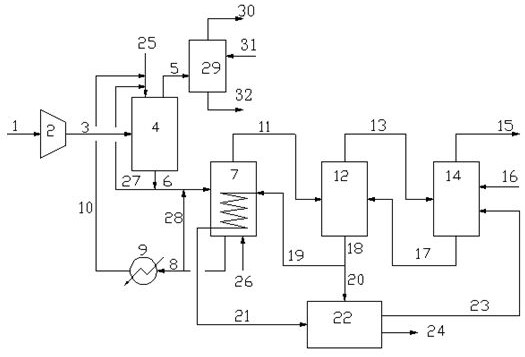
[0091] Acid gas volume Q=450Nm in a refinery 3 / h, pressure 0.7Mpa, where H 2 S volume fraction is 85%, CO 2 The volume fraction is 14%, and the remainder is hydrocarbons and other substances. use figure 1 The shown processing method and device process acid gas. Wherein, the hydrate decomposer adopts a conventional tank structure with heat exchange equipment inside, and the shell of the hydrate decomposer is provided with a stripping gas inlet pipeline.
[0092] The operating conditions and treatment effects during the treatment process are as follows: the hydrate working fluid consists of water, SDS accounting for 0.03% of the aqueous solution, polyethylene glycol accounting for 12% of the aqueous solution, diesel oil with a volume ratio of 1 / 2 to water, Composed of Span (sorbitan fatty acid ester) emulsifier with a molar ratio of 0.8% to water. The acid gas is pressurized by the compressor to 1.2Mpa and then introduced into the hydration reactor, where it reacts with t...
Embodiment 2
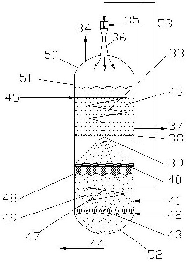
[0094] Same as Example 1, the difference is that using figure 2 In the structure of the decomposer, the volume ratio of the hydrate heating section of the hydrate decomposer to the hydrate decomposition and gasification section is 1 / 1, the liquid holdup in the hydrate heating section is 1 / 2 of the volume of this section, and the hydrate The liquid holding capacity of the decomposing gasification section is 1 / 2 of the total volume of this section, and the rupture partition assembly in the hydrate decomposer adopts a screen structure with an average hole diameter of 5mm.
[0095] Due to the use of the preferred hydrate decomposing device provided by the present invention, two stages of high-efficiency cascade heat exchange are performed, and the heat of the entire process is rationally utilized, and the working fluid can be decomposed (regenerated) under the same hydrate decomposing operating conditions as in Example 1 ) is more complete, to achieve the same effect as in Exampl...
Embodiment 3
[0097] Same as Example 2, except that the hydrate working fluid used is emulsified by water, SDS accounting for 0.03% of the mass fraction of the aqueous solution, diesel oil with a water volume ratio of 1 / 2, and Span with a water molar ratio of 0.8%. agent composition.
[0098] Under the same hydrate reactor operating conditions as in Example 2, the CO in the tail gas treated by the hydration reactor 2 The concentration is lower than 80%; after the hydrate-rich working fluid is treated by the hydrate decomposer, the CO in the gas 2 The concentration is about 5%, increasing the CO 2 form Na 2 CO 3 / NaHCO 3 The impact of substances such as NaHS on the continuous and stable operation of the NaHS production unit has increased the operational difficulty of the long-term operation of the device.
PUM
| Property | Measurement | Unit |
|---|---|---|
| diameter | aaaaa | aaaaa |
Abstract
Description
Claims
Application Information