Control device for machine tool performing oscillation cutting

一种控制装置、机床的技术,应用在自动控制装置、喂食装置、程序控制等方向,能够解决无法解决切割工具超过加工停止位置等问题

Active Publication Date: 2018-11-02
FANUC LTD
View PDF8 Cites 3 Cited by
  • Summary
  • Abstract
  • Description
  • Claims
  • Application Information

AI Technical Summary

Problems solved by technology

Therefore, it is sometimes impossible to solve the problem that the cutting tool exceeds the machining stop position

Method used


Image

  • Control device for machine tool performing oscillation cutting
  • Control device for machine tool performing oscillation cutting
  • Control device for machine tool performing oscillation cutting

Examples


Embodiment Construction

[0019] Hereinafter, embodiments of the present invention will be described with reference to the drawings. In the following drawings, the same reference signs are attached to the same components. For easy understanding, the scales of these drawings are appropriately changed. In addition, the form shown in drawing is an example for implementing this invention, and this invention is not limited to the form of illustration.

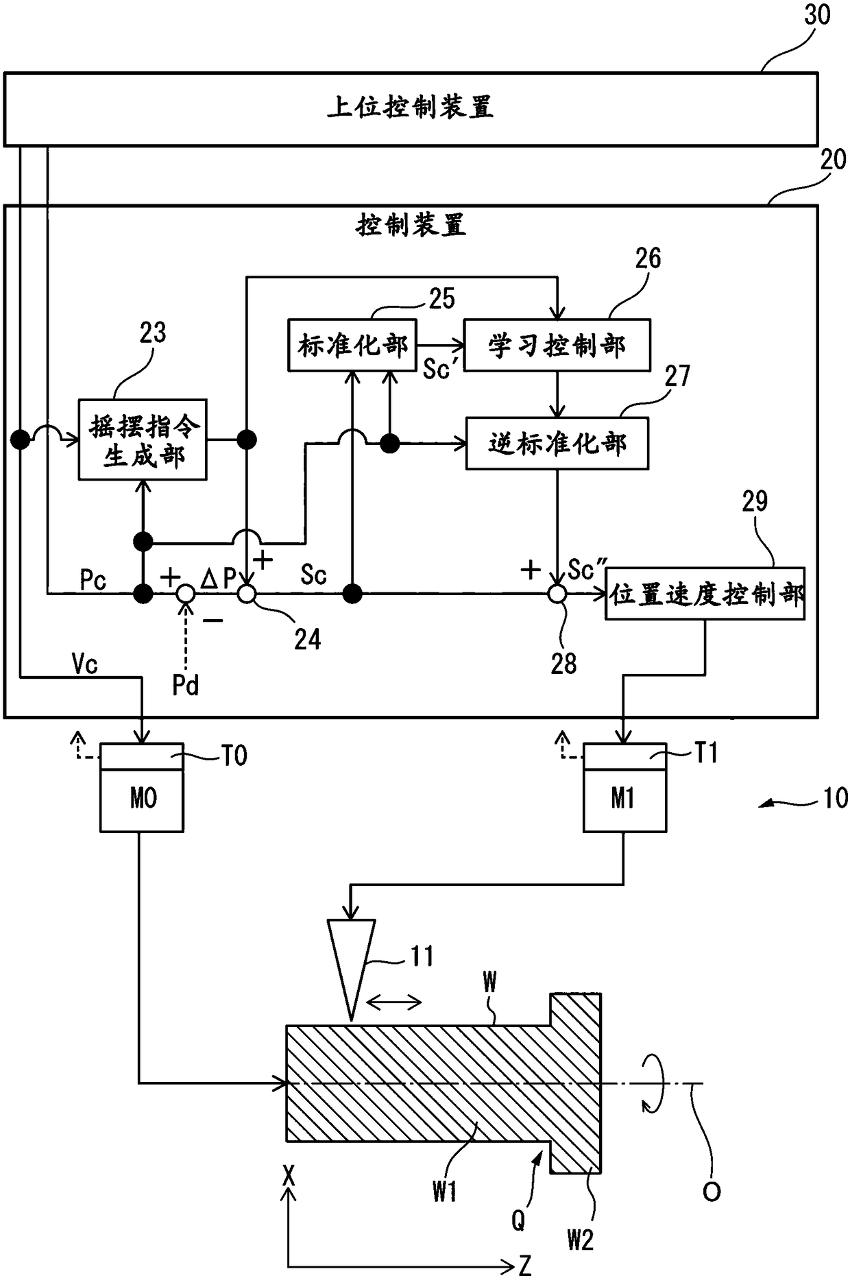
[0020] figure 1 It is a system diagram including the control device according to the first embodiment. Such as figure 1 As shown, the system 1 includes: a machine tool 10 , a control device 20 for controlling the machine tool 10 , and a host control device 30 connected to the control device 20 . The machine tool 10 has a tool 11 which cuts an outer or inner peripheral surface of a workpiece W which is at least partially rotationally symmetrical about an axis of rotation O. In addition, in figure 1 Among others, the axis of rotation of the workpiece W i...


PUM


Abstract

The present invention relates to a control device for a machine tool performing oscillation cutting. The control device for a machine tool includes an oscillation command generation part which generates an oscillation command for a fees axis, a first adding part which adds an oscillation command to a position deviation between a position command and the detected position of the fees axis to generate a resultant command, a normalization part for normalizing the resultant command, a learning control part that obtains a correction amount of the resultant command based on an oscillation phase obtained from the oscillation command and a normalized resultant command and which adds the correction amount to the resultant command, a denormalization part which denormalizes an output from the learning control part, and a second adding part for adding a denormalized output from the denormalization part to the resultant command.

Description

technical field [0001] The invention relates to a control device for a machine tool for rocking cutting. Background technique [0002] If chips are continuously generated when a workpiece is machined by a tool of a machine tool, there may be cases where the chips are entangled with the tool. Therefore, there is known a technique of intermittently cutting a workpiece by oscillating a tool (for example, refer to Japanese Patent No. 5033929 and Japanese Patent No. 5139592). [0003] However, in Japanese Patent No. 5033929 and Japanese Patent No. 5139592, it is not considered that the cutting process ends at a predetermined machining stop position. Therefore, there arises a problem that the cutting tool continues to oscillate beyond a predetermined machining stop position. Therefore, the following situation is disclosed in International Publication No. 2016 / 047485, that is, "when the above-mentioned cutting tool reaches the predetermined cutting tool processing stop position o...

Claims


Application Information

Patent Timeline
Patent Type & Authority Applications(China)
IPC IPC(8): B23Q15/12B23Q15/14
CPCB23Q15/12B23Q15/14G05B2219/31263G05B2219/37372G05B2219/45044G05B19/182
Inventor 於保勇作山本健太
Owner FANUC LTD
Why Eureka
Try Eureka