Multi-functional multi-arm coordinated operation control system for emergency rescue vehicle

A technology of control system and rescue vehicle, which is applied in the direction of load hanging components, cranes, transportation and packaging, etc., which can solve problems such as waste, difficulty in ensuring the consistency of working device actions, and low operating efficiency

Pending Publication Date: 2018-11-02
JIANGSU XCMG CONSTR MASCH RES INST LTD
View PDF11 Cites 2 Cited by
  • Summary
  • Abstract
  • Description
  • Claims
  • Application Information

AI Technical Summary

Problems solved by technology

[0003] In the existing rescue vehicles, generally only one kind of working arm is installed on one vehicle, and the control method for a single working arm is relatively simple. : The lifting operation of long strips of heavy objects) requires the coordination and cooperation of multiple vehicles and multiple operators to complete the rescue task. The cooperation of multiple operators is also complicated and cumbersome, resulting in low operating efficiency
This is not only a waste of rescue materials and manpower, but also causes excessive congestion to the space of the rescue site, which is not conducive to the smooth flow of the road.
[0004] In the existing technical scheme, when faced with the lifting operation of long strips of heavy objects at the rescue site, at least two rescue vehicles and two operators are required to cooperate with each other to complete the lifting operation of the heavy objects. There must be good communication between the hands, and it is difficult to ensure the consistency of the action of the working device when two vehicles lift heavy objects at the same time, which will inevitably affect the efficiency of the lifting operation
In addition, the simultaneous operation of two vehicles will inevitably cause excessive congestion to the space of the rescue site, which is not conducive to the smooth flow of the road.

Method used


Image

  • Multi-functional multi-arm coordinated operation control system for emergency rescue vehicle
  • Multi-functional multi-arm coordinated operation control system for emergency rescue vehicle
  • Multi-functional multi-arm coordinated operation control system for emergency rescue vehicle

Examples


Embodiment Construction

[0050] The present invention will be further described below in conjunction with specific examples.

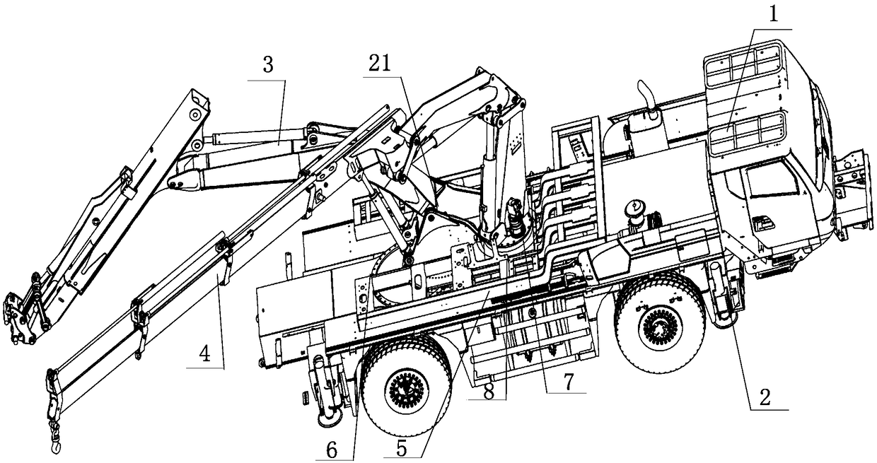
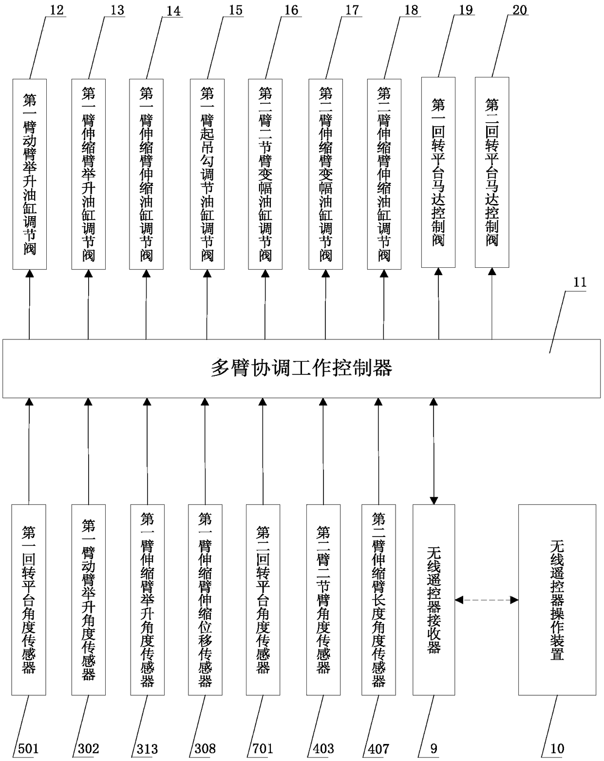
[0051] Such as figure 1 and figure 2 As shown, a control system for the coordinated work of multiple working arms of a multifunctional emergency rescue vehicle includes a vehicle main body 1, a working leg 2, a first working arm 3, a second working arm 4, and a second working arm for installing the first working arm. A slewing platform 5, a first slewing support 6 for connecting the vehicle body 1 and the first slewing platform 5, a second slewing platform 7 for installing the second working arm 4, and a second slewing platform 7 for connecting the first slewing platform and the second slewing platform The second slewing support 8 of the platform, the wireless remote control receiver 9, the wireless remote control operation device 10, the multi-arm coordinated work controller 11, the first arm boom lifting cylinder regulating valve 12, the first arm telescopic boom lifting c...


PUM


Abstract

The invention discloses a multi-functional multi-arm coordinated operation control system for an emergency rescue vehicle. A first rotary platform is installed on the main body of the vehicle, whereina first working arm is installed on the first rotary platform; a second rotary platform is installed on the first rotary platform, and a second working arm is installed on the second rotary platform;a first arm boom lifting cylinder regulating valve, a first arm telescopic boom lifting cylinder regulating valve, a first arm telescopic boom telescopic cylinder regulating valve, a first arm lifting hook adjustment cylinder regulating valve, a second arm second boom luffing cylinder regulating valve, a second arm telescopic boom luffing cylinder regulating valve, a second arm telescopic boom telescopic cylinder regulating valve, a motor control valve of the first rotary platform, a motor control valve of the second rotary platform, an angle sensor of the first rotary platform and an angle sensor of the second rotary platform are all connected with the multi-arm coordinated operation controller by signals. In this way, multiple arms of the multi-functional emergency rescue vehicle can lift long bar-shaped heavy objects efficiently, harmoniously, stably and safely.

Description

technical field [0001] The invention belongs to the technical field of engineering machinery, and in particular relates to a multi-arm coordinated operation control system for a multifunctional emergency rescue vehicle. Background technique [0002] The multi-functional emergency rescue vehicle is a special emergency rescue vehicle, which is mainly used in road clearance, ruins cleaning, barrier lake dredging, buried people and object rescue when natural geological disasters such as earthquakes and mudslides occur. Due to the characteristics of tight time, heavy tasks, and complex and changeable working conditions in emergency rescue operations, it is required that emergency rescue vehicles have multiple functions, that is to say, multiple functions or multiple working devices can be implemented on one vehicle. , so that rescue operations in various working conditions can be carried out. However, the current rescue vehicles generally only contain one working device. In the ...

Claims


Application Information

Patent Timeline
Patent Type & Authority Applications(China)
IPC IPC(8): B66C13/20B66C13/40B66C13/16B66C23/82B66C23/84B66C23/693B66C23/78
CPCB66C13/16B66C13/20B66C13/40B66C23/705B66C23/78B66C23/82B66C23/84
Inventor 赵斌汉京勇李刚元
Owner JIANGSU XCMG CONSTR MASCH RES INST LTD
Why Eureka
Try Eureka