
Biogas collection and control equipment

A technology for controlling equipment and biogas collection, applied in the field of biogas collection, can solve problems such as unavailability of dead gas, and achieve the effect of increasing gas storage space

Pending Publication Date: 2018-11-02
江含飞
View PDF0 Cites 0 Cited by
  • Summary
  • Abstract
  • Description
  • Claims
  • Application Information

AI Technical Summary

Problems solved by technology

[0004] The purpose of the present invention is to solve the problem of unusable dead gas in the hydraulic biogas fermentation room in the prior art, and propose a biogas collection control device

Method used


Image

  • Biogas collection and control equipment
  • Biogas collection and control equipment

Examples


Embodiment 1

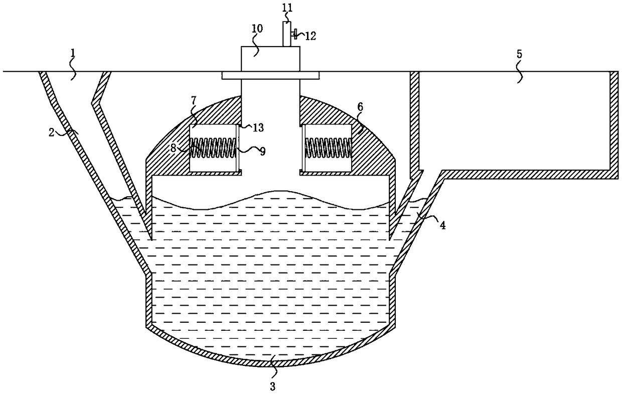
[0017] Such as figure 1 As shown, a biogas collection control device of the present invention includes a biogas fermentation tank 6, a biogas fermentation chamber 3 is provided in the biogas fermentation tank 6, a feed pipe 2 is installed at one end of the biogas fermentation tank 6, and the feed pipe 2 is connected to the biogas The fermentation chamber 3 is connected, the end of the feed pipe 2 away from the biogas fermentation tank 6 is equipped with a feed funnel 1, and the feed funnel 1 is connected with the feed pipe 2, and the end of the biogas fermentation tank 6 is equipped with a discharge pipe 4, and the outlet The material pipe 4 communicates with the biogas fermentation chamber 3, the end of the discharge pipe 4 away from the biogas fermentation tank 6 is installed with a collection box 5, and the collection box 5 is connected with the discharge pipe 4, and the top of the biogas fermentation tank 6 is equipped with a cover 10. An air outlet pipe 11 is installed on...

Embodiment 2

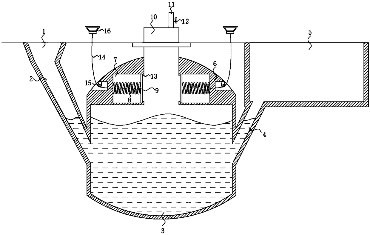
[0022] Such as figure 2 As shown, this embodiment adds a stay rope, a fixed pulley and a pull ring on the basis of Embodiment 1, thereby realizing the artificial regulation of the baffle 9 and increasing the flexibility of use. One end of the baffle 9 close to the cavity 7 is fixedly connected There is a stay rope 14, and the end of the stay rope 14 away from the baffle plate 9 runs through the biogas fermentation tank 6 and is fixedly connected with a pull ring 16. There is a slot on the biogas fermentation tank 6, and a fixed pulley 15 is installed in the slot, and the stay rope 14 passes through it. Over fixed pulley 15.


PUM


Abstract

The invention discloses biogas collection and control equipment. The biogas collection and control equipment comprises a biogas fermentation tank, wherein a biogas fermentation cavity is formed in thebiogas fermentation tank; a feeding pipe is mounted at one end of the biogas fermentation tank; the feeding pipe is communicated with the biogas fermentation cavity; a feeding funnel is mounted at one end, far away from the biogas fermentation tank, of the feeding pipe; the feeding funnel is communicated with the feeding pipe; a discharging pipe is mounted at one end of the biogas fermentation tank; the discharging pipe is communicated with the biogas fermentation cavity; a material collection box is mounted at one end, far away from the biogas fermentation tank, of the discharging pipe; thematerial collection box is communicated with the discharging pipe; a cover body is mounted at the top end of the biogas fermentation tank; a gas outlet pipe is mounted on the cover body; a valve is mounted on the gas outlet pipe; two cavities are symmetrically formed in an inner wall of the biogas fermentation tank. According to the biogas collection and control equipment disclosed by the invention, the cavities are formed; baffle plates are mounted in the cavities so that the space of dead gas can be reduced; in a biogas fermentation and generation process, a compression spring can be drivento be compressed, so that a gas storage space is enlarged.

Description

technical field [0001] The invention relates to the technical field of biogas collection, in particular to biogas collection control equipment. Background technique [0002] Hydraulic biogas digesters are the earliest and most numerous pond shapes in my country. They are summarizing the "three combinations", "round, small, shallow", "movable cover", "straight pipe feeding", "middle layer discharge", etc. It is formed on the basis of the pool built by the masses and comprehensively improved. Hydraulic biogas digesters are the earliest and most numerous pond shapes in my country. They are summarizing the "three combinations", "round, small, shallow", "movable cover", "straight pipe feeding", "middle layer discharge", etc. It is formed on the basis of the pool built by the masses and comprehensively improved. The "three-in-one combination" means that the toilet, pigsty and biogas digester are integrated into one, and human and animal manure can be cleaned directly into the biog...

Claims


Application Information

Patent Timeline
Patent Type & Authority Applications(China)
IPC IPC(8): C12M1/107
CPCC12M21/04C12M23/36
Inventor 江含飞
Owner 江含飞
Learn More