Hydraulic valve for continuous casting and rolling production line of steel mill

A continuous casting and rolling, hydraulic valve technology, applied in the field of hydraulic valves, can solve the problems of shortening the service life of hydraulic oil, intensified oxidation of hydraulic oil, failure of hydraulic oil, etc., and achieve the effect of shortening service life

Inactive Publication Date: 2018-11-02
ANHUI DERUIMAI HYDRAULIC MASCH CO LTD
View PDF0 Cites 0 Cited by
  • Summary
  • Abstract
  • Description
  • Claims
  • Application Information

AI Technical Summary

Problems solved by technology

[0003] The hydraulic valve used in the continuous casting and rolling production line of the steel plant needs to withstand high temperature when working. The high temperature makes the viscosity of the hydraulic oil smaller, the viscosity is too low, the leakage of the hydraulic system increases, the efficiency decreases, and even the hydraulic system cannot work normally, and the high temperature makes the hydraulic oil The oxidation of the hydraulic oil is intensified, and some ketones, acids, colloids, asphaltene and other substances are gradually formed in the hydraulic oil, which will pollute the hydraulic oil and shorten the service life of the hydraulic oil.
When the hydraulic oil is oxidized to a certain extent, the hydraulic oil will fail and cannot be used

Method used


Image

  • Hydraulic valve for continuous casting and rolling production line of steel mill
  • Hydraulic valve for continuous casting and rolling production line of steel mill
  • Hydraulic valve for continuous casting and rolling production line of steel mill

Examples


Embodiment Construction

[0018] In order to make the technical means, creative features, goals and effects achieved by the present invention easy to understand, the present invention will be further elaborated below in conjunction with specific embodiments and accompanying drawings, but the following embodiments are only preferred embodiments of the present invention, not all . Based on the examples in the implementation manners, other examples obtained by those skilled in the art without making creative efforts all belong to the protection scope of the present invention.

[0019] Specific embodiments of the present invention will be described below in conjunction with the accompanying drawings.

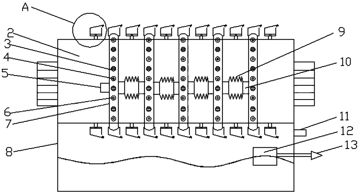
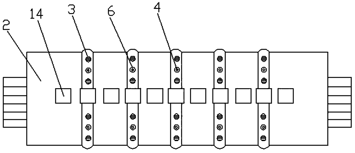
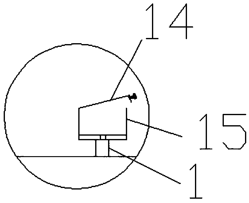
[0020] Such as Figure 1-3 As shown, a hydraulic valve for a continuous casting and rolling production line in a steel mill includes a hydraulic valve body 2, and a plurality of insert rods 1 are arranged on the top and bottom surfaces of the hydraulic valve body 2 along its length direction, and each inser...


PUM


Abstract

The invention relates to the field of hydraulic valves and in particular relates to a hydraulic valve for a continuous casting and rolling production line of a steel mill. The hydraulic valve comprises a hydraulic valve body, wherein the hydraulic valve body is provided with a plurality of insertion bars; a U-shaped water bag clamping groove is inserted onto each insertion bar; a top cover is arranged on each U-shaped water bag clamping groove; a jack is formed in the top cover; multiple closed rubber water bags are arranged on the hydraulic valve body in a sleeving manner; the rubber water bags are arranged in the U-shaped water bag clamping grooves positioned on the top surface and the bottom surface in a sleeving manner; water outlets are formed in the rubber water bags; two adjacent water outlets are communicated by virtue of a folding hose; a water inlet pipe is arranged on the rubber water bags positioned on the outer side. According to the hydraulic valve disclosed by the invention, a cooling device is arranged on the hydraulic valve, so that the problems that the hydraulic valve for the continuous casting and rolling production line of the steel mill needs to bear a high temperature during operation, the viscosity of hydraulic oil is reduced and the viscosity is too low due to the high temperature, leakage of a hydraulic system is increased and the efficiency is reducedare solved, and the defects that the hydraulic oil oxidizes to produce impurities due to the high temperature and the hydraulic oil is contaminated are overcome.

Description

technical field [0001] The invention relates to the field of hydraulic valves, in particular to a hydraulic valve for continuous casting and rolling production lines in steel mills. Background technique [0002] The hydraulic control valve is referred to as a hydraulic valve. The function in the hydraulic system is to control and adjust the flow direction, pressure and flow of the oil in the hydraulic system, so that the actuator and its driven working mechanism can obtain the required movement direction, thrust and movement speed. Any hydraulic system, no matter how simple it is, cannot lack hydraulic valves; hydraulic mechanical equipment with the same process purpose can be used in different combinations of hydraulic valves to form a variety of hydraulic system solutions with completely different oil circuit structures. [0003] The hydraulic valve used in the continuous casting and rolling production line of the steel plant needs to withstand high temperature when workin...

Claims


Application Information

Patent Timeline
Patent Type & Authority Applications(China)
IPC IPC(8): F15B13/02F15B21/04B21B1/46
CPCF15B13/02B21B1/46F15B21/042
Inventor 吴兆松赵丙龙
Owner ANHUI DERUIMAI HYDRAULIC MASCH CO LTD
Why Eureka
Try Eureka