
Motor and Dual Mass Flywheel

A dual-mass flywheel and flywheel technology, applied in flywheels and other directions, can solve problems such as low engine speed, resonance impact, damage, etc., and achieve the effect of meeting anti-resonance requirements

Active Publication Date: 2020-05-01
SAIC MOTOR
View PDF4 Cites 0 Cited by
  • Summary
  • Abstract
  • Description
  • Claims
  • Application Information

AI Technical Summary

Problems solved by technology

[0004] However, in some specific working conditions of the engine, such as engine start-up, engine idling rotation, and low engine speed, the vibration frequency generated by the engine rotation is close to or reaches the resonance frequency of the dual-mass flywheel, causing system resonance, and the resonance will produce a large Impact, which will reduce the life of the dual-mass flywheel and its surrounding components or even damage them

Method used


Image

  • Motor and Dual Mass Flywheel
  • Motor and Dual Mass Flywheel
  • Motor and Dual Mass Flywheel

Examples


no. 1 example

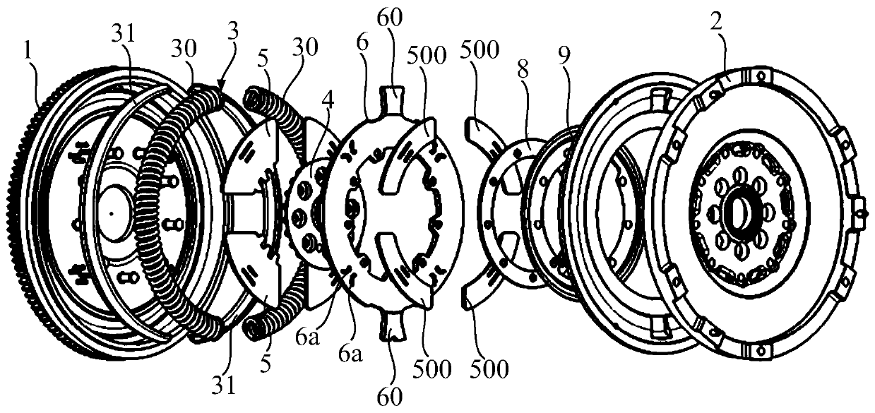
[0048] A car includes an engine, a gearbox, and a dual-mass flywheel connected between the engine and the gearbox. The dual-mass flywheel can transmit the output torque of the engine to the gearbox. refer to figure 1 The dual-mass flywheel can include a main flywheel 1 and an auxiliary flywheel 2 arranged in sequence along the axial direction, and an elastic damping mechanism 3 and a clutch can be arranged between the main flywheel 1 and the auxiliary flywheel 2, and the elastic damping mechanism 3 can be used in the main flywheel. The flywheel 1 and the auxiliary flywheel 2 are elastically deformed when they rotate relative to each other, so as to achieve the purpose of vibration reduction.

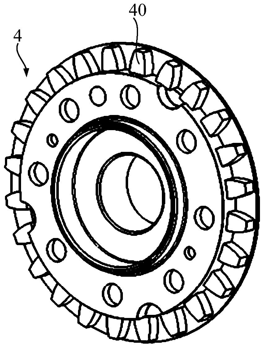
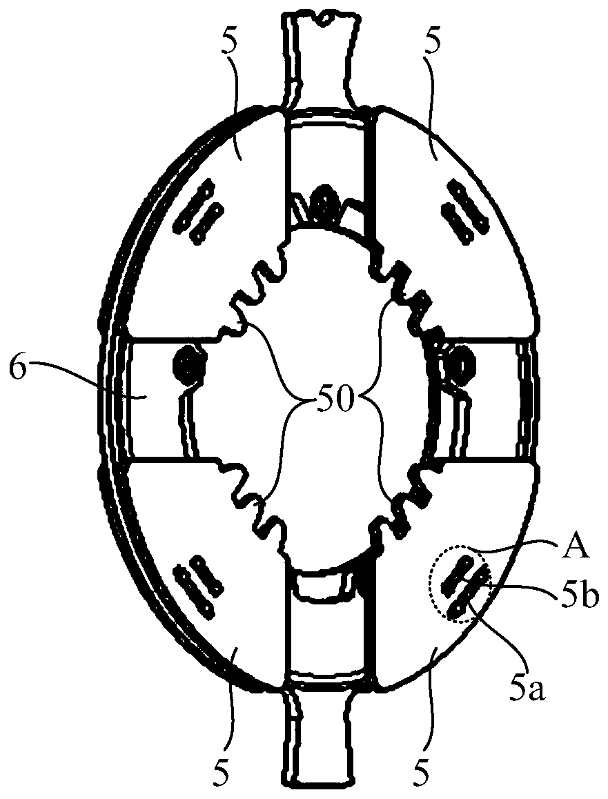
[0049]The clutch part includes a fixed part 4 and a movable part 5, one of the movable part 5 and the fixed part 4 is connected to the main flywheel 1 and the other is connected to the auxiliary flywheel 2, which may include: the fixed part 4 is arranged on the auxiliary flywheel 2 and ...

no. 2 example

[0079] refer to Figure 6 , the movable part 15 can be provided with an insertion part 150, and the fixed part 14 can be provided with a receiving part 14a;

[0080] When the insertion part 150 is not inserted into the receiving part 14a, the fixed part 14 and the movable part 15 can be separated;

[0081] When the insertion part 150 is inserted into the receiving part 14a, the fixed part 14 and the movable part 15 may be combined.

[0082] From separation to combination, there is relative rotation between the fixed part 14 and the movable part 15, the insertion part 150 can first contact the outer peripheral surface of the movable part 15, and slide along the outer peripheral surface to fall into the receiving part 14a, and then the insertion part 150 is blocked by the side wall of the receiving portion 14a, so that the fixed part 14 and the movable part 15 are combined.

[0083] The fixed part 14 has an outer peripheral surface facing the movable part 15 , and the movable ...


PUM


Abstract

The invention relates to a car and a dual mass flywheel. The dual mass flywheel comprises a main flywheel and an auxiliary flywheel which are sequentially arranged in the axial direction; an elastic damping mechanism and a clutch piece are arranged between the main flywheel and the auxiliary flywheel, the elastic damping mechanism can generate elastic deformation when the main flywheel and the auxiliary flywheel rotate relatively; the clutch piece comprises a fixing piece and a movable piece, one of the movable piece and the fixing piece is connected to the main flywheel, and the other one ofthe movable piece and the fixing piece is connected to the auxiliary flywheel; and in the radial direction of the dual mass flywheel, the movable piece and the fixed piece are relatively arranged, andthe movable piece can move relative to the fixed piece. The movable piece and the fixed piece can be combined to enable the main flywheel and the auxiliary flywheel to rotate synchronously; the movable piece can be separated from the fixed piece under the gradually-increased centrifugal force effects along with increase of the rotating speed of the dual mass flywheel, and the main flywheel and the auxiliary flywheel are separated. The dual mass flywheel in the technical scheme can reduce the resonance risk of an engine during low rotating speed.

Description

technical field [0001] The invention relates to the technical field of automobiles, in particular to an automobile and a dual-mass flywheel. Background technique [0002] Existing automotive transmission systems usually include a dual-mass flywheel, which is used to transmit the output torque of the engine, and can reduce the torsional vibration generated when the engine rotates. A traditional dual-mass flywheel can include a main flywheel, an auxiliary flywheel and an elastic damping mechanism between the two. The dual-mass flywheel is connected to the output end of the engine through the main flywheel, and connected to the input end of the gearbox through the auxiliary flywheel. The main flywheel and the auxiliary flywheel are connected by bearings so that the main flywheel and the auxiliary flywheel can rotate relatively. The output torque of the engine is transmitted to the elastic damping mechanism by the main flywheel, and the elastic damping mechanism further transmi...

Claims


Application Information

Patent Timeline
Patent Type & Authority Patents(China)
IPC IPC(8): F16F15/30
CPCF16F15/30
Inventor 葛凤龙葛柱洪
Owner SAIC MOTOR
Learn More