Ball valve capable of prolonging service lifetime

A ball valve and life-span technology, applied in the direction of using liquid cleaning methods, valve devices, cleaning methods and appliances, etc., can solve the problem of adhesions on the inner wall of the ball valve cavity, blockage of the ball valve, and adhesions on the inner wall of the ball valve cavity, etc. Problems, easy to use, prolong service life, good cleaning effect

Inactive Publication Date: 2018-11-02
四川威卡自控仪表有限公司
View PDF0 Cites 2 Cited by
  • Summary
  • Abstract
  • Description
  • Claims
  • Application Information

AI Technical Summary

Problems solved by technology

[0004] The technical problem to be solved by the present invention is that there will be adher

Method used


Image

  • Ball valve capable of prolonging service lifetime

Examples


Embodiment 1

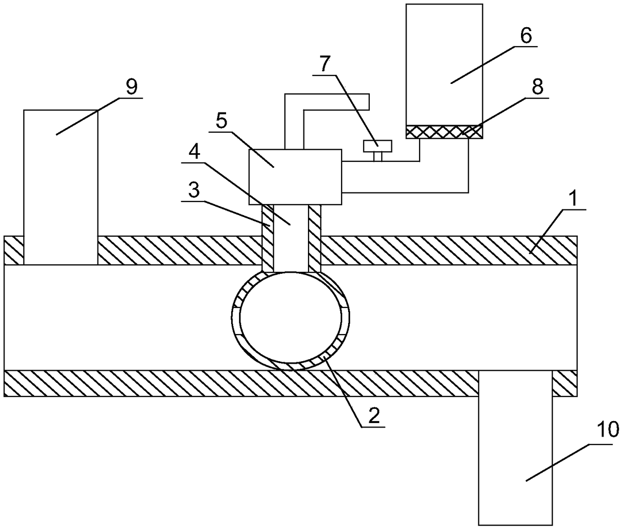
[0023] Such as figure 1 As shown, the ball valve with extended service life of the present invention includes a valve body 1, a valve core 2, and a valve stem 3. The valve core 2 is located inside the valve body 1, and the valve stem 3 is vertically connected above the valve body 1 and connected to the valve body. The core 2 is fixedly connected, the interior of the valve core 2 is provided with a cavity for fluid to flow through, and the interior of the valve stem 3 is provided with a channel 4 communicating with the internal cavity of the valve core 2, and the channel 4 is along the axial direction of the valve stem 3 Through the valve stem 3, the top of the valve stem 3 is installed with a control valve 5 communicating with the channel 4, the outlet of the control valve 5 is communicated with the channel 4, and the inlet of the control valve 5 is communicated with a container 6 with cleaning agent inside. 6 is located on the side of the control valve 5 and above the inlet p...

Embodiment 2

[0026] Based on Embodiment 1, a flow meter 7 is installed at the inlet end of the control valve 5 . The flowmeter can reasonably measure the cleaning agent that passes into the valve core, which can not only ensure that a sufficient amount of cleaning agent enters the valve core, but also avoid the waste of cleaning agent.

Embodiment 3

[0028] Based on the above embodiments, the side wall of the valve body 1 close to its inlet end communicates with a first branch pipe 9 , and the side wall of the valve body 1 near its outlet end communicates with a second branch pipe 10 .

[0029] The cooperation between the first branch pipe and the second branch pipe can discharge the cleaning agent inside the valve core, and can also pass clean water into the valve core to clean the valve core. The first branch pipe and the second branch pipe provide another flow path for the ball valve .


PUM


Abstract

The invention discloses a ball valve capable of prolonging service lifetime. The ball valve comprises a valve body, a valve core and a valve rod. The valve core is located in the interior of the valvebody. The valve rod is vertically connected on the valve body and fixedly connected with the valve core. The interior of the valve core is equipped with a cavity supplying forfluids to pass through.The interior of the valve rod is equipped with a channel communicating with the cavity in the interior of the valve core. The channel penetrates through the valve rod in the axial direction of the valve rod. The top of the valve rod is provided with a control valve communicating with the channel. An outlet of the control valve communicates with the channel. An inlet of the control valve is equipped with a container internally holding a cleaning agent in a communicating manner. The container is located on the side surface of the control valve and located above an inlet end of the control valve.A traditional ball valve structure is changed. The problem that the valve core is blocked is resolved.

Description

technical field [0001] The invention relates to a ball valve, in particular to a ball valve with extended service life. Background technique [0002] In my country, ball valves are widely used in petroleum refining, long-distance pipelines, chemical industry, papermaking, pharmaceuticals, water conservancy, electric power, municipal, steel and other industries, and occupy a pivotal position in the national economy. It has the action of rotating 90 degrees. The cock body is a sphere with a circular through hole or channel passing through its axis. The ball valve is mainly used to cut off, distribute and change the flow direction of the medium in the pipeline. It only needs to be rotated 90 degrees and a small rotational torque can be closed tightly. Ball valves are most suitable for on-off and shut-off valves, V-type ball valves. [0003] The spool of the ball valve is a sphere with a cavity inside, and some fluids with high viscosity will partially adhere to the inner wall...

Claims


Application Information

Patent Timeline
IPC IPC(8): F16K5/06F16K5/08B08B9/08B08B3/08
CPCF16K5/06B08B3/08B08B9/0804F16K5/08
Inventor 罗淸云袁平仁胡碧文邓显会
Owner 四川威卡自控仪表有限公司
Why Eureka
Try Eureka