
Air conditioner and control method and control device for blowing waste heat thereof

A control method and air-conditioning technology, applied in space heating and ventilation, space heating and ventilation details, heating methods, etc., can solve problems such as low outlet air temperature, reduce fan noise, speed up pressure balance, and improve experience Effect

Active Publication Date: 2018-11-02
GD MIDEA AIR-CONDITIONING EQUIP CO LTD +1
View PDF7 Cites 12 Cited by
  • Summary
  • Abstract
  • Description
  • Claims
  • Application Information

AI Technical Summary

Problems solved by technology

[0004] The embodiment of the present application provides an air conditioner and its control method and device for blowing waste heat, which solves the technical problem in the prior art that the temperature of the air outlet is too low due to the time process of blowing waste heat, and realizes the operating wind speed of the indoor fan. and the adjustment of the waste heat blowing time

Method used


Image

  • Air conditioner and control method and control device for blowing waste heat thereof
  • Air conditioner and control method and control device for blowing waste heat thereof
  • Air conditioner and control method and control device for blowing waste heat thereof

Examples


Embodiment 1

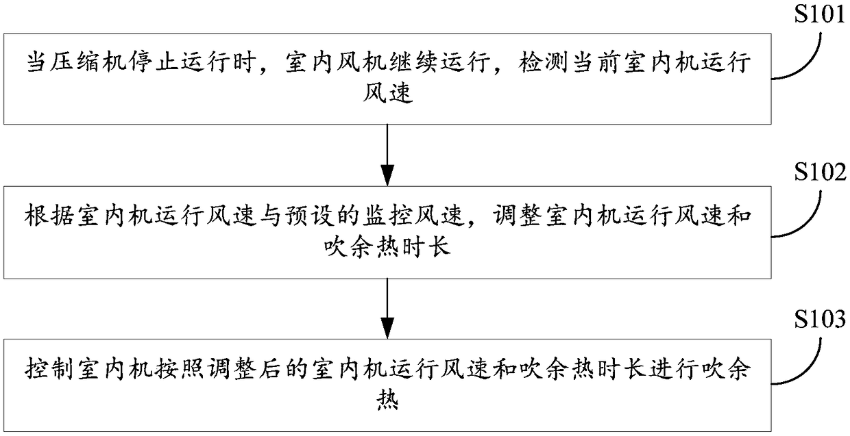
[0025] figure 1 It is a flowchart of a control method for blowing waste heat from an air conditioner according to an embodiment of the present invention. like figure 1 As shown, the control method for blowing waste heat from the air conditioner according to the embodiment of the present invention includes the following steps after the heating mode of the air conditioner ends:

[0026] S101: When the compressor stops running, the indoor fan continues to run, and the current running wind speed of the indoor unit is detected.

[0027] S102: According to the running wind speed of the indoor unit and the preset monitoring wind speed, adjust the running wind speed of the indoor unit and the duration of blowing waste heat.

[0028] S103: Control the indoor unit to blow waste heat according to the adjusted operating wind speed of the indoor unit and the blowing time of waste heat.

[0029] That is to say, after the heating mode of the air conditioner ends, that is, after the heatin...

Embodiment 2

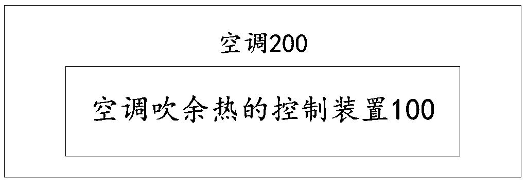
[0056] figure 2 It is a schematic block diagram of a control device for blowing waste heat from an air conditioner according to an embodiment of the present invention. The control device 100 for blowing waste heat of an air conditioner according to the embodiment of the present invention includes: a detection module 10 , an adjustment module 20 and a control module 30 .

[0057] Among them, the detection module 10 is used to detect the running wind speed of the indoor unit used by the indoor fan to blow waste heat to the air-conditioning coil at the current moment when the compressor stops running after the air-conditioning heating mode ends; the adjustment module 20 is used to The operating wind speed of the indoor unit and the preset monitoring wind speed are used to adjust the operating wind speed of the indoor unit and the duration of blowing waste heat; the control module 30 is used to control the indoor unit to blow waste heat according to the adjusted operating wind sp...


PUM


Abstract

The invention discloses an air conditioner and a control method and a control device for blowing waste heat thereof. After a heating mode of the air conditioner, the method also comprises the following steps: when a compressor stops operating, detecting the current operating air speed of an indoor unit as an indoor fan operates continuously; adjusting the operating air speed and the waste heat blowing duration of the indoor unit according to the operating air speed of the indoor unit and a preset monitoring air speed; and controlling the indoor unit to blow waste heat according to the adjustedoperating air speed and the waste heat blowing duration of the indoor unit. The technical problem that the air outlet temperature is too low as a result of the waste heat blowing time process is solved, and the operating air speed and the waste heat blowing duration of the indoor unit are adjusted.

Description

technical field [0001] The invention relates to the technical field of air conditioners, in particular to an air conditioner and a control method and device for blowing waste heat thereof. Background technique [0002] After the compressor of the air conditioner is stopped, there is still residual heat in the indoor coil, and the temperature of the coil is still high. If the indoor unit fan stops running at this time, the system pressure will not reach equilibrium as soon as possible. Blow waste heat to the coil of the indoor unit after the compressor stops running. [0003] However, there are problems in related technologies that the temperature of the air outlet is too low due to the excessively long blowing time of the waste heat, and the wind speed is high and the noise is loud when blowing the waste heat, which affects the user experience. Contents of the invention [0004] The embodiment of the present application provides an air conditioner and its control method a...

Claims


Application Information

Patent Timeline
Patent Type & Authority Applications(China)
IPC IPC(8): F24F11/86F24F11/89F24F11/74F24F11/64F24F13/24F24F11/77
CPCF24F11/64F24F11/74F24F11/77F24F11/86F24F11/89F24F13/24F24F2013/247Y02B30/70
Inventor 曾威谭周衡
Owner GD MIDEA AIR-CONDITIONING EQUIP CO LTD
Learn More