A corner vertical forced convection heat exchange device

A technology of forced convection and heat exchange device, applied in indirect heat exchangers, heat exchanger types, heat exchanger shells, etc. Air purification and circulation, avoiding local overheating, and improving air quality

Active Publication Date: 2020-09-04
CHINA UNIV OF MINING & TECH
View PDF8 Cites 0 Cited by
  • Summary
  • Abstract
  • Description
  • Claims
  • Application Information

AI Technical Summary

Problems solved by technology

[0002] At present, radiator heating is the most widely used heating method in China, but there are some shortcomings in the heating effect of radiators.
The radiator will cause the local temperature to be too high, the heat dissipation will not be rapid and uneven, the indoor space will cause a large temperature difference, the temperature near the radiator is high, and the temperature far away from the radiator is too low, and the experience comfort is not high
In winter, in general, in order to reduce the temperature loss, the doors and windows need to be closed indoors, but this will cause the indoor and outdoor air to not circulate, the air flow is poor and the quality is poor, which is not conducive to people breathing fresh air

Method used


Image

  • A corner vertical forced convection heat exchange device
  • A corner vertical forced convection heat exchange device
  • A corner vertical forced convection heat exchange device

Examples


specific Embodiment

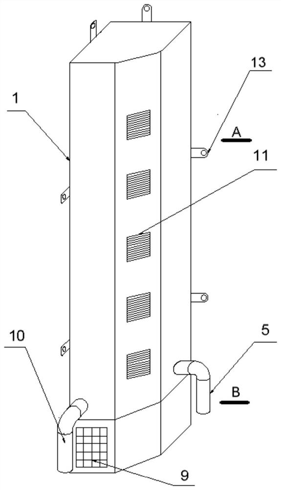
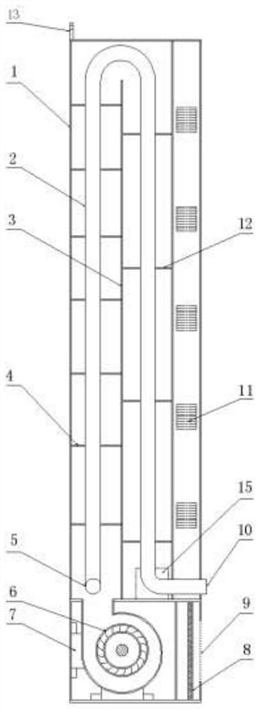
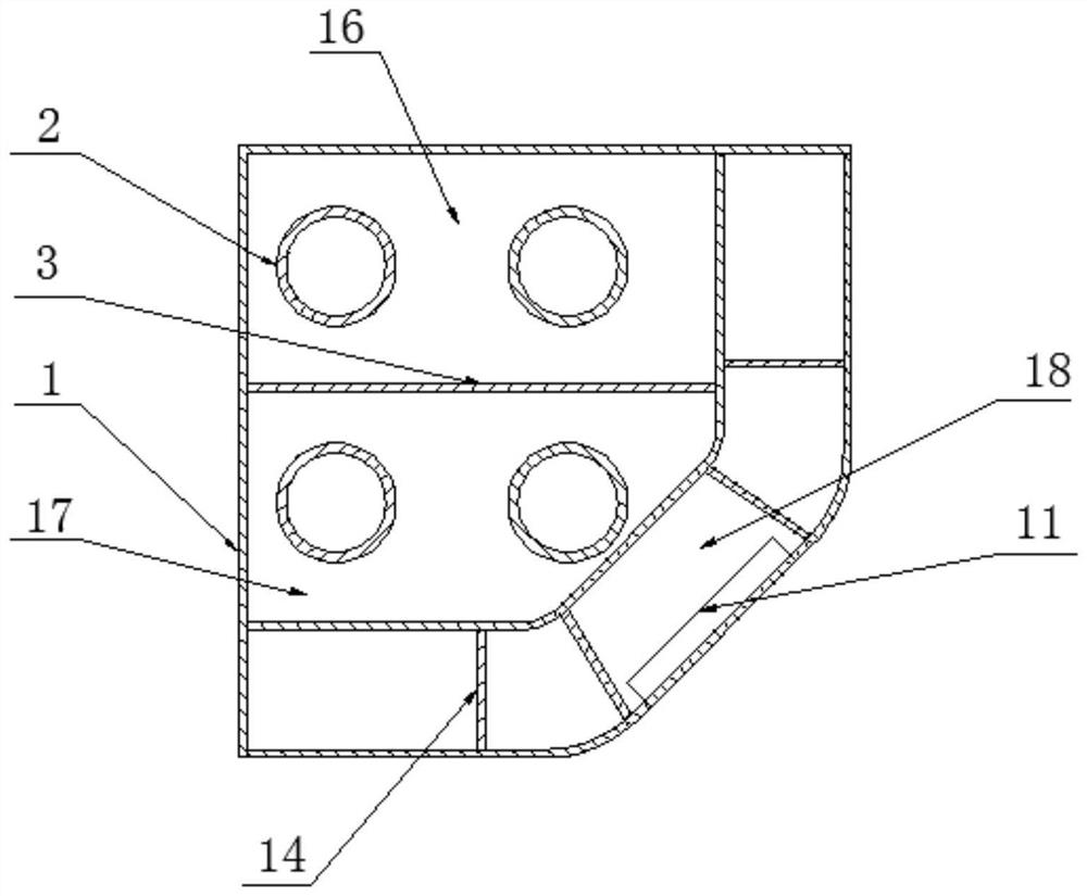
[0026] Specific embodiment: this device is placed in the corner position of the room, press figure 1 As shown in the three-dimensional structure, the left side and the rear side are respectively kept in contact with the two wall surfaces at the corner, and then the fixing ears 13 at various positions are used to fix the device to the wall, so as to ensure the installation stability of the device . The total height of the device is about 3m, and its horizontal cross-sectional size is 200×200mm, the occupied area is small, and the spatial position of the corner of the wall can be reasonably utilized. A fan 6 is installed on the lower part of the housing 1, the air outlet of the fan 6 is directly connected to the heat exchange air duct on the upper part, the air inlet of the fan 6 communicates with the air inlet 9 opened on the housing 1, and the filter 8 is installed on both sides. position between them. When the fan is working, the air is sucked in from the air inlet 9, and a...


PUM


Abstract

The invention provides a wall corner vertical type forced-convection heat transfer device which comprises a shell, a radiating pipe, a vertical baffle, a baffle plate, a draught fan, a filter and a fixed plate. The shell is divided into two parts, and the upper part of the shell is divided into an inner shell and an outer shell. The vertical baffle and the radiating pipe are arranged in the innershell, wherein a water inlet opening is formed at one end of the lower portion of the radiating pipe, and a backwater opening is formed at the other end of the lower portion of the radiating pipe. Thedraught fan and the filter are arranged in the lower part of the shell, wherein the draught fan and the filter are fixed by a clamping seat of the draught fan. An air outlet of the draught fan is faced to a lateral radiating pipe of one side of the water inlet opening, and the air outlet of the draught fan is connected with the bottom end of the rear heat exchange air duct in a direct communicating mode. The lower part of a shell panel is provided with an air inlet faced to the filter. The air purified and filtered by the filter is sucked into a heat exchange channel outside the radiating pipe through the draught fan, the air flow flows around the radiating pipe and the baffle plate located in the heat exchange channel, and the air flow and hot water in the radiating pipe carry out the heat exchange, to meet the requirement of the temperature of out wind. According to the wall corner vertical type forced-convection heat transfer device, indoor temperature rise and air purification andcirculation are realized. The device is simple in structure, convenient to install and maintain, environmentally friendly and capable of saving energy.

Description

technical field [0001] The invention relates to a corner vertical heat exchange device, in particular to a wall corner vertical forced convection heat exchange device suitable for indoors, and belongs to the technical field of heating and the like. Background technique [0002] At present, radiator heating is the most widely used heating method in China, but there are some shortcomings in the heating effect of radiators. The radiator will cause the local temperature to be too high, the heat dissipation will not be rapid and uneven, and the indoor space will cause a large temperature difference. The temperature near the radiator is high, and the temperature far away from the radiator is too low, and the experience comfort is not high. In winter, in general, in order to reduce temperature loss, doors and windows need to be closed indoors, but this will cause indoor and outdoor air not to circulate, the air flow is poor and the quality is poor, which is not conducive to people ...

Claims


Application Information

Patent Timeline
Patent Type & Authority Patents(China)
IPC IPC(8): F28D1/047F28F9/24B01D46/10
CPCB01D46/10F28D1/047F28F9/24
Inventor 粟文兵闫小康李娟孟诗淇王友韦景校刘康远张灵怡
Owner CHINA UNIV OF MINING & TECH
Why Eureka
Try Eureka