Face light source backlight module and liquid crystal display panel

A backlight module and surface light source technology, which is applied in optics, nonlinear optics, instruments, etc., can solve the problems of uneven brightness, haze particles that cannot achieve a better light mixing effect, and affect the overall brightness of surface light sources. Transmittance and brightness, conducive to thin design, and improve the effect of light mixing uniformity

Active Publication Date: 2018-11-02
WUHAN CHINA STAR OPTOELECTRONICS TECH CO LTD
View PDF11 Cites 15 Cited by
  • Summary
  • Abstract
  • Description
  • Claims
  • Application Information

AI Technical Summary

Problems solved by technology

[0003] like figure 1 and figure 2 As shown, there is a direct-type backlight module in the prior art, which adopts an array-type LED surface light source. The direct-type backlight module includes an LED substrate 100, an LED light-emitting chip 200, a fluorescent film 300, a diffusion sheet 400 and a brightness enhancement Diaphragm 500, because the LED light is close to the Lambertian distribution, the center brightness is higher, and the surrounding brightness is lower, so it is easy to produce uneven brightness during the lighting process of the direct-lit backlight module
At present, people often use diffusers to mix light or add scattering haze particles to the fluorescent film to mix light, but the addition of the film layer will reduce the penetration rate of the overall surface light source, affect the overall brightness of the surface light source, and the haze particles in the fluorescent film will also reduce Unable to achieve better light mixing effect

Method used


Image

  • Face light source backlight module and liquid crystal display panel
  • Face light source backlight module and liquid crystal display panel
  • Face light source backlight module and liquid crystal display panel

Examples


Embodiment Construction

[0027] In order to further illustrate the technical means adopted by the present invention and its effects, the following describes in detail in conjunction with preferred embodiments of the present invention and accompanying drawings.

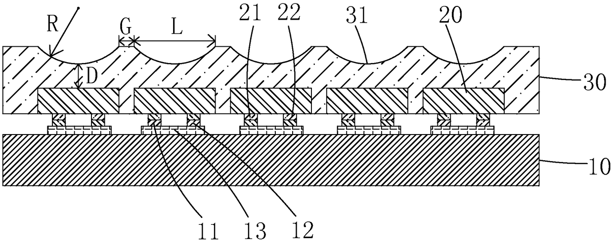
[0028] see image 3 , is a schematic diagram of the first embodiment of the surface light source backlight module of the present invention, including a Mini LED substrate 10, several Mini LED chips 20 arranged at intervals on the Mini LED substrate 10, and covering the several Mini LED chips 20 of the fluorescent film 30, the surface of the fluorescent film 30 away from the plurality of Mini LED chips 20 is provided with several microstructures 31 to improve the light mixing effect of the surface light source backlight module and improve the uniformity of brightness in the surface. Therefore, compared with the traditional backlight module, there is no need to arrange an optical film on the fluorescent film 30 to achieve the effect of uniform l...


PUM

PropertyMeasurementUnit
lengthaaaaaaaaaa

Abstract

The invention provides a face light source backlight module and a liquid crystal display panel. The face light source backlight module comprises a Mini LED substrate, a plurality of Mini LED chips arranged on the Mini LED substrate at intervals and a fluorescent film covering the Mini LED chips, wherein a plurality of microstructures are arranged on the surface, away from one side of the Mini LEDchips, of the fluorescent film so that the Mini LED chips can achieve large-angle light emergence, the light mixing uniformity of the face light source backlight module is improved, the purpose of saving an optical film to achieve uniform light mixing is achieved, accordingly the penetration and brightness of a face light source are improved, and meanwhile thinning design of the face light sourcebacklight module is facilitated.

Description

technical field [0001] The invention relates to the field of display technology, in particular to a surface light source backlight module and a liquid crystal display panel. Background technique [0002] With the development of display technology, liquid crystal display (Liquid Crystal Display, LCD) and other flat display devices are widely used in mobile phones, TVs, Various consumer electronic products such as personal digital assistants, digital cameras, notebook computers, and desktop computers have become the mainstream of display devices. Most of the liquid crystal display devices currently on the market are backlight liquid crystal display devices, which include a liquid crystal display panel and a backlight module (Backlight Module). The working principle of the liquid crystal display panel is to place liquid crystal molecules between two parallel glass substrates. There are many vertical and horizontal small wires between the two glass substrates. The direction of ...

Claims


Application Information

Patent Timeline
Patent Type & Authority Applications(China)
IPC IPC(8): G02F1/13357
CPCG02F1/133603G02F1/133606G02F1/133607G02F1/133614
Inventor 杨勇查国伟崔宏青
Owner WUHAN CHINA STAR OPTOELECTRONICS TECH CO LTD
Why Eureka
Try Eureka