
Display panel

A display panel and display area technology, applied in the direction of instruments, electrical digital data processing, electrical components, etc., can solve the problems of occupying the design space of the frame 11, weak anti-ESD ability, and increasing the difficulty of the panel

Inactive Publication Date: 2018-11-02
WUHAN CHINA STAR OPTOELECTRONICS TECH CO LTD
View PDF8 Cites 24 Cited by
  • Summary
  • Abstract
  • Description
  • Claims
  • Application Information

AI Technical Summary

Problems solved by technology

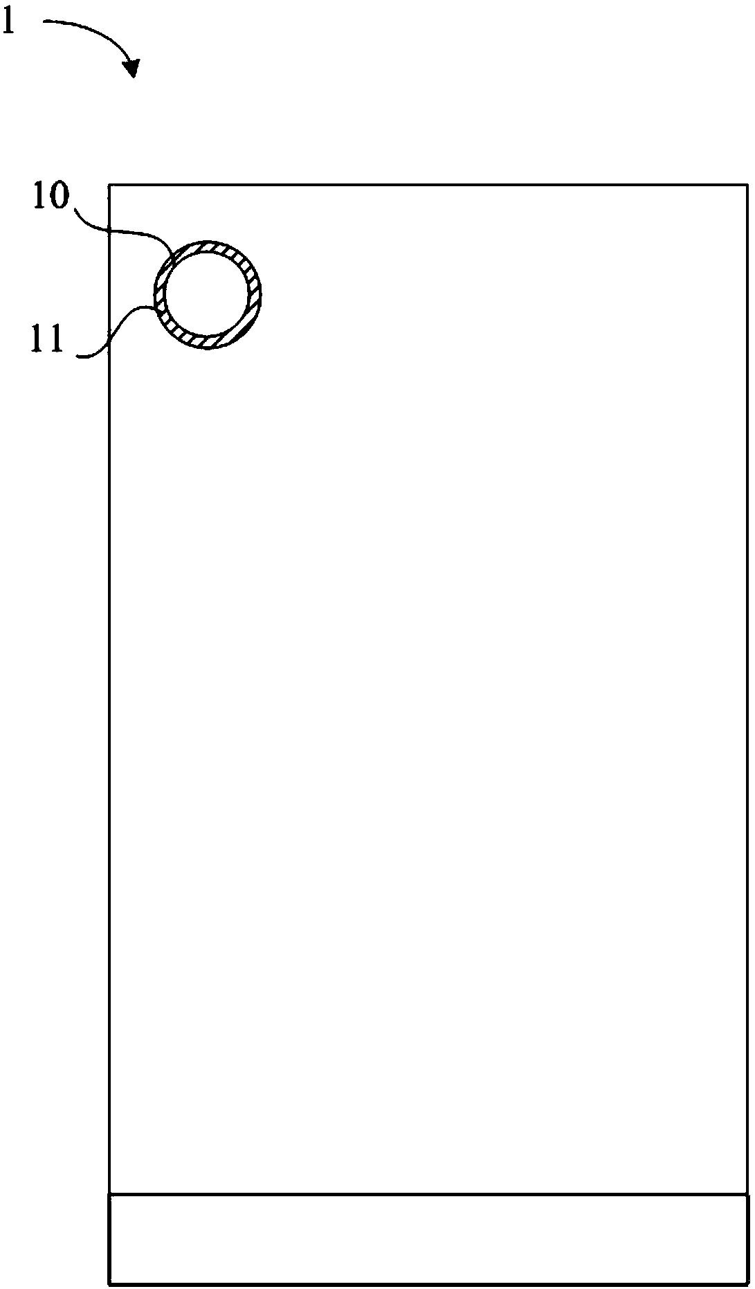
Based on the current design scheme, there are effective arc-shaped metal traces connecting data lines, gate lines, and touch signal lines at the frame 11, which occupy most of the design space of the frame 11.
Moreover, the frame 11 usually adopts a narrow frame design and occupies part of the display area of ​​the display panel 1, so that there cannot be a ground wire design like the left and right frames at the frame 11 to protect the metal traces from being accumulated inside the display panel 1 during the ESD test. Excessive static electricity can cause circuit damage, especially in the ESD reliability test, the anti-ESD ability of frame 11 is weak
In addition, in the era of pursuing a full screen and extremely narrow bezel design, the bezel 11 around the opening 10 will also be compressed, which puts forward higher requirements for reliability testing (ESD test at the bezel 11) and increases the difficulty of panel design.

Method used


Image

  • Display panel
  • Display panel
  • Display panel

Examples


Embodiment Construction

[0022] In order to make the above and other objectives, features, and advantages of the present disclosure more comprehensible, preferred embodiments of the present disclosure will be exemplified below in detail with reference to the attached drawings.

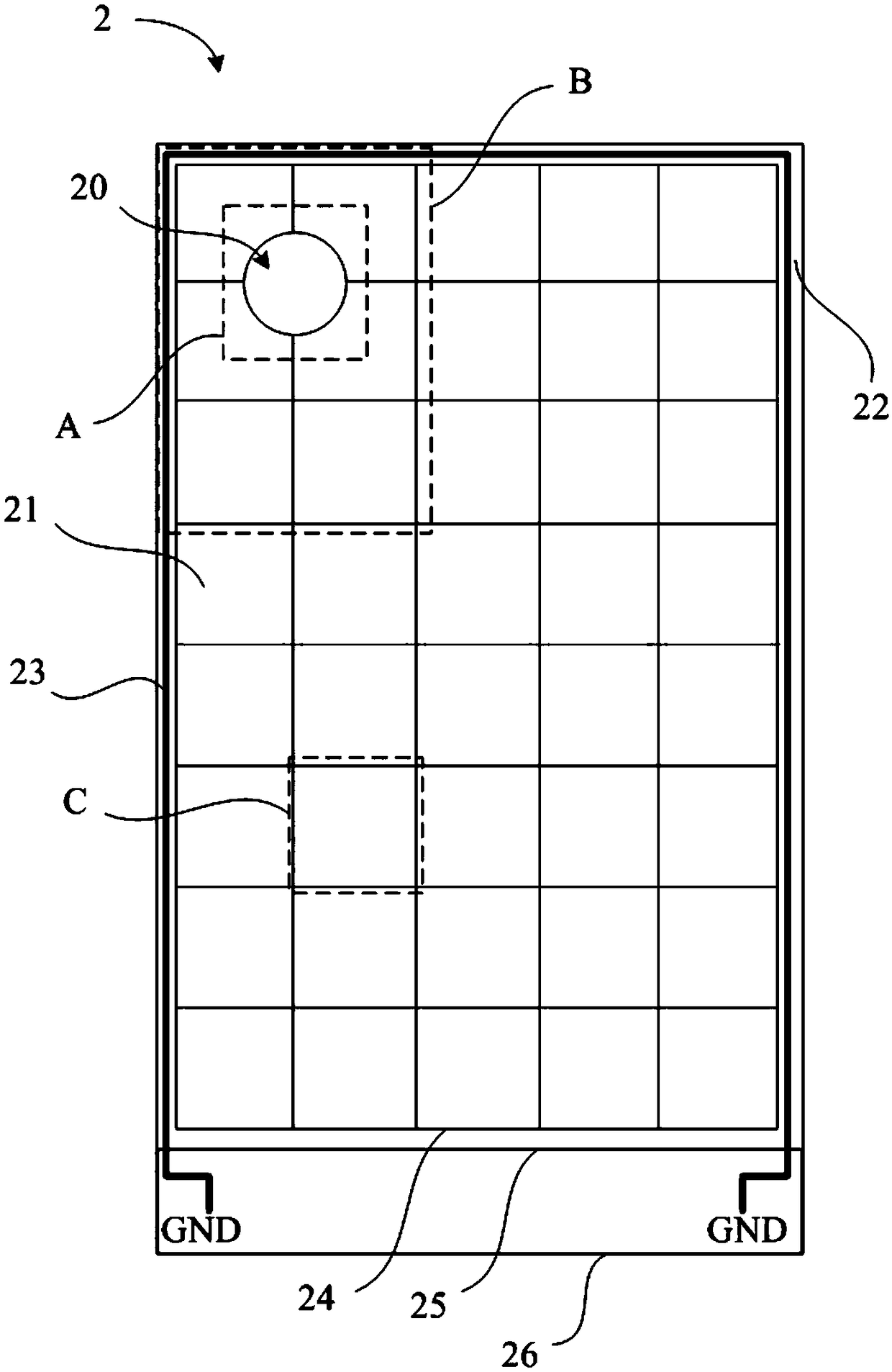
[0023] Please refer to figure 2 , which shows a schematic diagram of the display panel 2 according to the first preferred embodiment of the present disclosure, which specifically shows a schematic diagram of the touch control scheme of the display panel 2 with openings in the display area and the related wiring design. The display panel 2 disclosed in this disclosure is provided for the purpose of realizing the full-screen design of the whole machine and retaining the layout position of the front camera, wherein the display panel 2 is provided with an opening 20 at the position of the upper panel, that is, at the position corresponding to the front camera . Moreover, the display panel 2 can be LCD, OLED, etc., and can be app...


PUM


Abstract

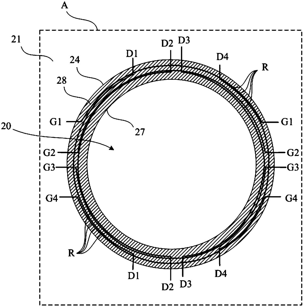
The invention discloses a display panel. The display panel is characterized by comprising a display area, a first non-display area, a trepanning, a second non-display area and an anti-static discharging protection circuit, wherein the display area is provided with multiple display units arranged in an array; the first non-display area surrounds the display area; the trepanning is formed in an areain the display area; the second non-display area is located between the display area and the trepanning, and the second non-display area is internally provided with multiple arc-shaped wirings used for being connected with corresponding data cables, gate lines and touch signal lines respectively; the anti-static discharging protection circuit comprises a suspension joint metal wiring, and the suspension joint metal wiring is arranged on the periphery of the trepanning and located in the second non-display area. The anti-static discharging protection circuit is arranged on the second non-display area so as to improve the ESD resistance capacity of the touch signal lines on the second non-display area, thereby ensuring the reliability of the display panel provided with the trepanning in thedisplay area.

Description

technical field [0001] The present disclosure relates to a display panel, in particular to a display panel with a hole design in a display area. Background technique [0002] In order to realize the full-screen design of the whole machine and preserve the layout position of the front camera, a display panel with a hole design in the display area (Active Area) has been developed. Please refer to figure 1 , which shows a schematic diagram of a conventional display panel 1 having an opening 10 design in the display area. The opening 10 is provided on the upper surface of the display panel 1 , that is, part of the display unit is removed from the position corresponding to the front camera in the upper surface. In the current hole design scheme, part of the display unit is usually removed in a circular hole 10 design, and a frame 11 is designed around the hole 10, which is similar to the non-display area of ​​the left and right frames to provide related transmission line settin...

Claims


Application Information

Patent Timeline
Patent Type & Authority Applications(China)
IPC IPC(8): G09F9/00G06F3/041H05K9/00
CPCH05K9/0067G06F3/0412G09F9/00H10K59/40H10K59/126H10K59/131
Inventor 洪光辉
Owner WUHAN CHINA STAR OPTOELECTRONICS TECH CO LTD
Learn More