Thin pipe cutting device

A cutting device and thin tube technology, applied in the field of mechanical processing, can solve the problems of difficult to guarantee cutting accuracy and thin tube deformation, and achieve the effect of ensuring quality and not easy to deform

Inactive Publication Date: 2018-11-06
ANHUI HAODING METAL PROD LIMITED
View PDF0 Cites 1 Cited by
  • Summary
  • Abstract
  • Description
  • Claims
  • Application Information

AI Technical Summary

Problems solved by technology

[0002] Usually, when cutting thin-walled pipes such as white iron pipes, the pipes to be cut are clamped and fixed between two splints with adjustable spacing, and then the pipes to be cut are cut with a rotary cutting knife. Since the pipes to be cut are in a rigid During the clamping, the thin tube may be deformed during the cutting process, the cutting accuracy is difficult to guarantee, and the cutting speed is also limited

Method used


Image

  • Thin pipe cutting device

Examples


Embodiment Construction

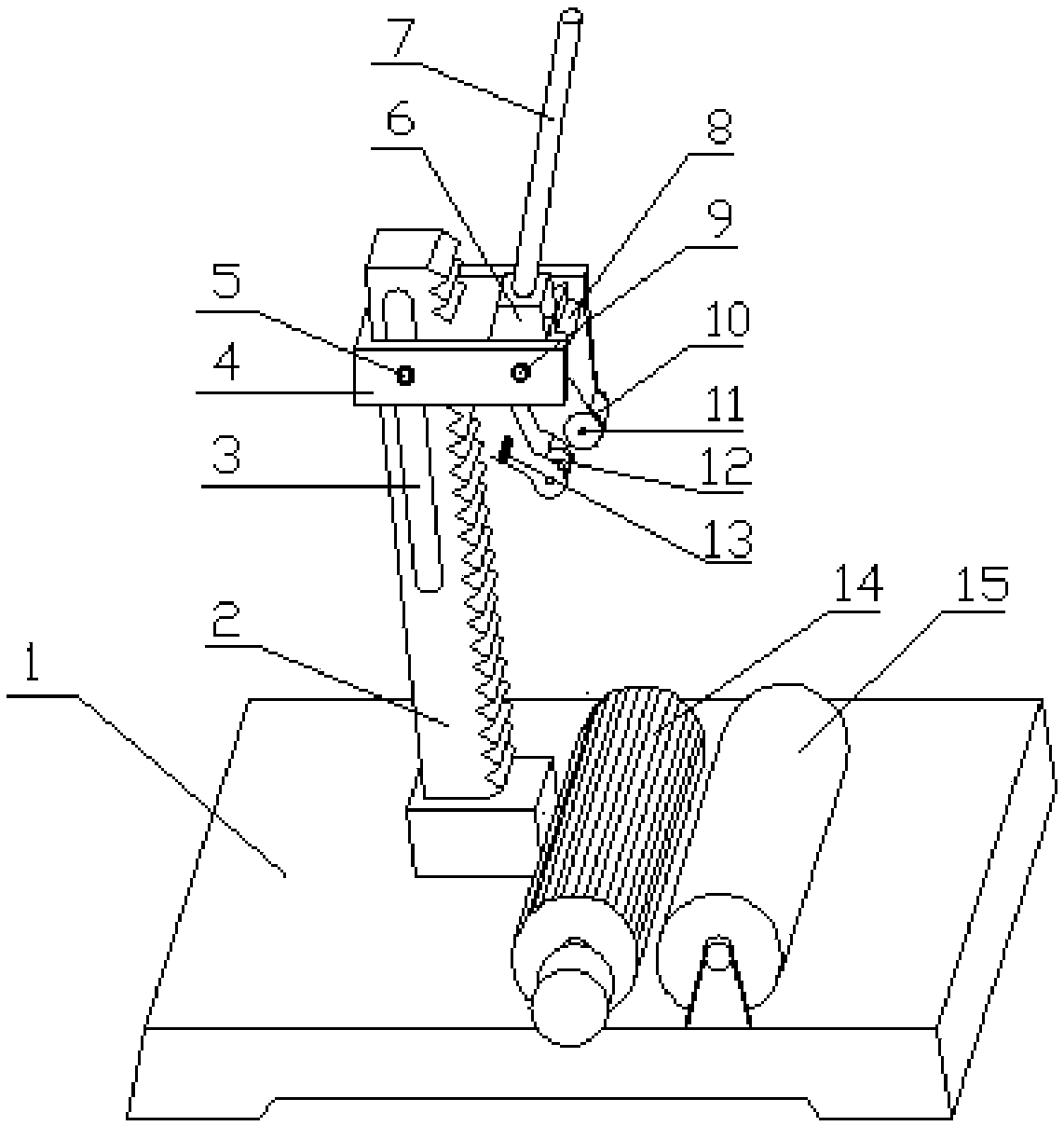
[0023] figure 1 Among them, the driving roller 14 and the driven roller 15 form the bearing part, and other parts form the cutting part, and these two parts are installed in the vicinity of the base 1;

[0024] The active roller is connected to the power transmission mechanism, which can be a motor or a combination of a motor and a transmission system (not shown in the figure), to drive the active roller to rotate;

[0025] The driving roller 14 and the driven roller 15 are horizontally installed on the base, and there is a gap suitable for placing the pipe to be cut between the driving roller and the driven roller;

[0026] The surface of the active roller 14 is covered with a rubber layer, and the rubber layer is provided with a grid to increase the surface friction, which is beneficial to drive the pipe to be cut to rotate;

[0027] The rack 2 is installed vertically on the base and is located on the side of the tube, and the tooth surface of the rack 2 faces the direction...


PUM


Abstract

The invention discloses a thin pipe cutting device. The thin pipe cutting device comprises a base, a pipe supporting part and a cutting part; the pipe supporting pipe comprises a driving roller and adriven roller; and the cutting part comprises a rack, a slide groove, a slide sleeve, a positioning pin, a gear seat, a gear, a gear shaft, a handle seat, a handle, a cutter, a cutter holder, a pressing wheel and a torsional spring. In the cutting process, a pipe is driven by the driving roller to be in a rotary cutting stage and is not prone to being deformed, and the cutting quality can be ensured.

Description

technical field [0001] The invention relates to a thin tube cutting device, in particular to a thin tube cutting device, which belongs to the field of mechanical processing. Background technique [0002] Usually, when cutting thin-walled pipes such as white iron pipes, the pipes to be cut are clamped and fixed between two splints with adjustable spacing, and then the pipes to be cut are cut with a rotary cutting knife. Since the pipes to be cut are in a rigid During the clamping, the thin tube may be deformed during the cutting process, the cutting accuracy is difficult to guarantee, and the cutting speed is also limited. Contents of the invention [0003] The object of the present invention is a thin tube cutting device with less deformation during the cutting process. [0004] In order to achieve the above object, the present invention adopts the following technical solutions: [0005] A thin tube cutting device, comprising a base, a tube supporting part, and a cutting...

Claims


Application Information

Patent Timeline
IPC IPC(8): B23D21/00B23D33/02
CPCB23D21/00B23D33/02
Inventor 李久宁
Owner ANHUI HAODING METAL PROD LIMITED
Why Eureka
Try Eureka