
Pipe support device

A technology for supporting devices and pipes, applied in pipe shearing devices, shearing devices, accessories of shearing machines, etc., can solve the problems of high maintenance costs, unsuitable cams, cracking of cams, etc. Improved performance and easy adjustment

Pending Publication Date: 2018-11-06
FOSHAN HONGSHI LASER TECH CO LTD
View PDF14 Cites 5 Cited by
  • Summary
  • Abstract
  • Description
  • Claims
  • Application Information

AI Technical Summary

Problems solved by technology

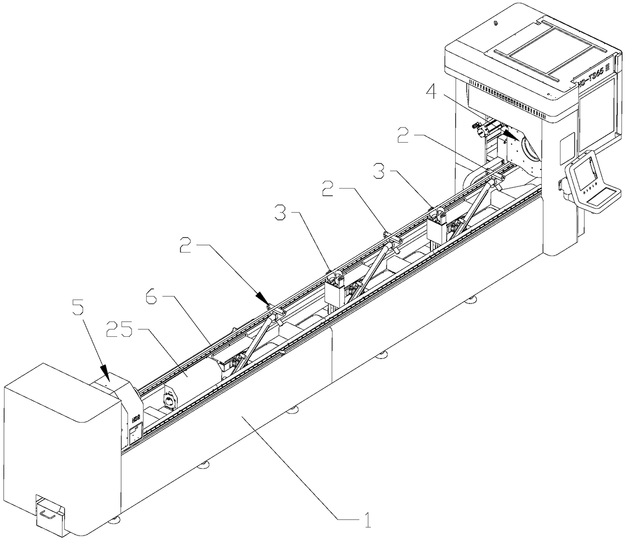
[0002] At present, the support for the pipe on the pipe cutting machine body on the market basically uses the linear follow-up support component of the connecting rod as the support. However, the light pipe will swing left and right in the horizontal direction.
[0003] However, there is another structure in the prior art. After the air cylinder or motor is used to lift it into place, the profiling concave wheel structure is used to support the pipe by adjusting the angle of the concave wheel. However, the concave wheel is not suitable for heavy pipe support. , because the heavy pressure of the pipe will cause greater friction to the concave wheel, which will intensify the wear of the concave wheel. In addition, the overweight pipe may also cause the concave wheel to crack, so the concave wheel is only suitable for the support of small and light tubes effect, and the profiling of the concave wheel takes a long time, resulting in high maintenance costs in the later period
[0004] At present, the support structures of pipe cutting machine bodies on the market have certain limitations in use, so a pipe support device with wide adaptability is needed

Method used


Image

  • Pipe support device
  • Pipe support device
  • Pipe support device

Examples


Embodiment Construction

[0043]In order to make the purpose, technical solutions and advantages of the present invention clearer, the present invention will be described in further detail below in conjunction with the examples, but the scope of protection claimed by the present invention is not limited to the following specific examples.

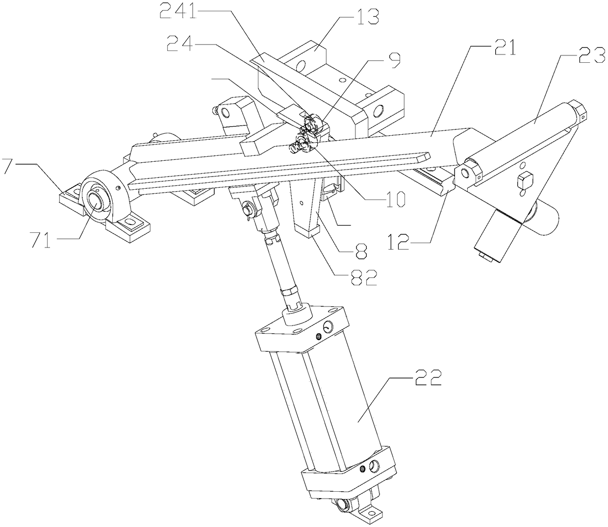
[0044] refer to figure 1 and figure 2 , this embodiment discloses a pipe support device, including a support bed 1, on which a plurality of sets of linear support assemblies 2 and concave wheel support assemblies 3 are arranged along the conveying direction of the pipe 6, and a plurality of sets of linear support assemblies 2 Alternately arranged with the concave wheel support assembly 3, the two ends of the support bed 1 along the pipe conveying direction are respectively provided with a front chuck 4 and a rear chuck 5, and the front chuck 4 and the rear chuck 5 are used for clamping and placing on a linear The pipe material 6 on the support assembly 2 and the c...


PUM


Abstract

The invention discloses a pipe support device. According to the scheme, the pipe support device comprises a support bed body, wherein a plurality of groups of linear support assemblies and a pluralityof groups of concave wheel support assemblies are arranged on the support bed body in a conveying direction for pipes; a front chuck and a rear chuck are arranged at the two ends of the support bed body separately; and the linear support assemblies and the concave wheel support assemblies are alternately arranged at intervals. When the pipes are supported through the linear support assemblies andthe concave wheel support assemblies which are alternately arranged on the support bed body, the linear support assemblies are capable of reducing the up-down swing of the pipes, the concave wheel support assemblies are capable of reducing the left-right swing of the pipes, so that the machining accuracy is improved by virtue of the advantages of the two types of support assemblies, and the applicability of the support device is improved; and due to the special arrangement for the linear support assemblies, when each horizontal slide block moves a certain length in the horizontal direction, aroller on each support rod is adjusted by a length which is the same as the length of the horizontal slide block in the vertical direction, and the adjustment is convenient.

Description

technical field [0001] The invention relates to the field of auxiliary devices for pipe cutting machines, in particular to a pipe support device. Background technique [0002] At present, the support for the pipe on the pipe cutting machine body on the market basically adopts the linear follow-up support assembly of the connecting rod as the support, but the light pipe will swing left and right in the horizontal direction. [0003] However, there is another structure in the prior art. After the air cylinder or motor is used to lift it into place, the profiling concave wheel structure is used to support the pipe by adjusting the angle of the concave wheel. However, the concave wheel is not suitable for heavy pipe support. , because the heavy pressure of the pipe will cause greater friction to the concave wheel, which will intensify the wear of the concave wheel. In addition, the overweight pipe may also cause the concave wheel to crack, so the concave wheel is only suitable f...

Claims


Application Information

Patent Timeline
Patent Type & Authority Applications(China)
IPC IPC(8): B23D33/02B23D21/00
CPCB23D21/00B23D33/02
Inventor 常勇
Owner FOSHAN HONGSHI LASER TECH CO LTD
Learn More