
Cutting machine tool for metal component machining

A technology of metal components and cutting machine tools, which is applied in the direction of metal processing machinery parts, metal processing equipment, manufacturing tools, etc., can solve the problems of reducing the work efficiency of operators, affecting the surface processing quality of components, and being unable to achieve synchronous actions, etc., to achieve improved Work efficiency, the effect of ensuring the quality of processing

Inactive Publication Date: 2018-11-06
陈发军
View PDF0 Cites 4 Cited by
  • Summary
  • Abstract
  • Description
  • Claims
  • Application Information

AI Technical Summary

Problems solved by technology

[0005] Aiming at the deficiencies of the prior art, the present invention provides a cutting machine tool for metal component processing, which solves the problem that the existing cleaning method is mostly that the operator cleans up when the cutting machine is stopped, and cannot perform synchronous actions. Affects the processing quality of the surface of the component, and also reduces the work efficiency of the operator

Method used


Image

  • Cutting machine tool for metal component machining
  • Cutting machine tool for metal component machining
  • Cutting machine tool for metal component machining

Examples


Embodiment Construction

[0022] The following will clearly and completely describe the technical solutions in the embodiments of the present invention with reference to the accompanying drawings in the embodiments of the present invention. Obviously, the described embodiments are only some, not all, embodiments of the present invention. Based on the embodiments of the present invention, all other embodiments obtained by persons of ordinary skill in the art without making creative efforts belong to the protection scope of the present invention.

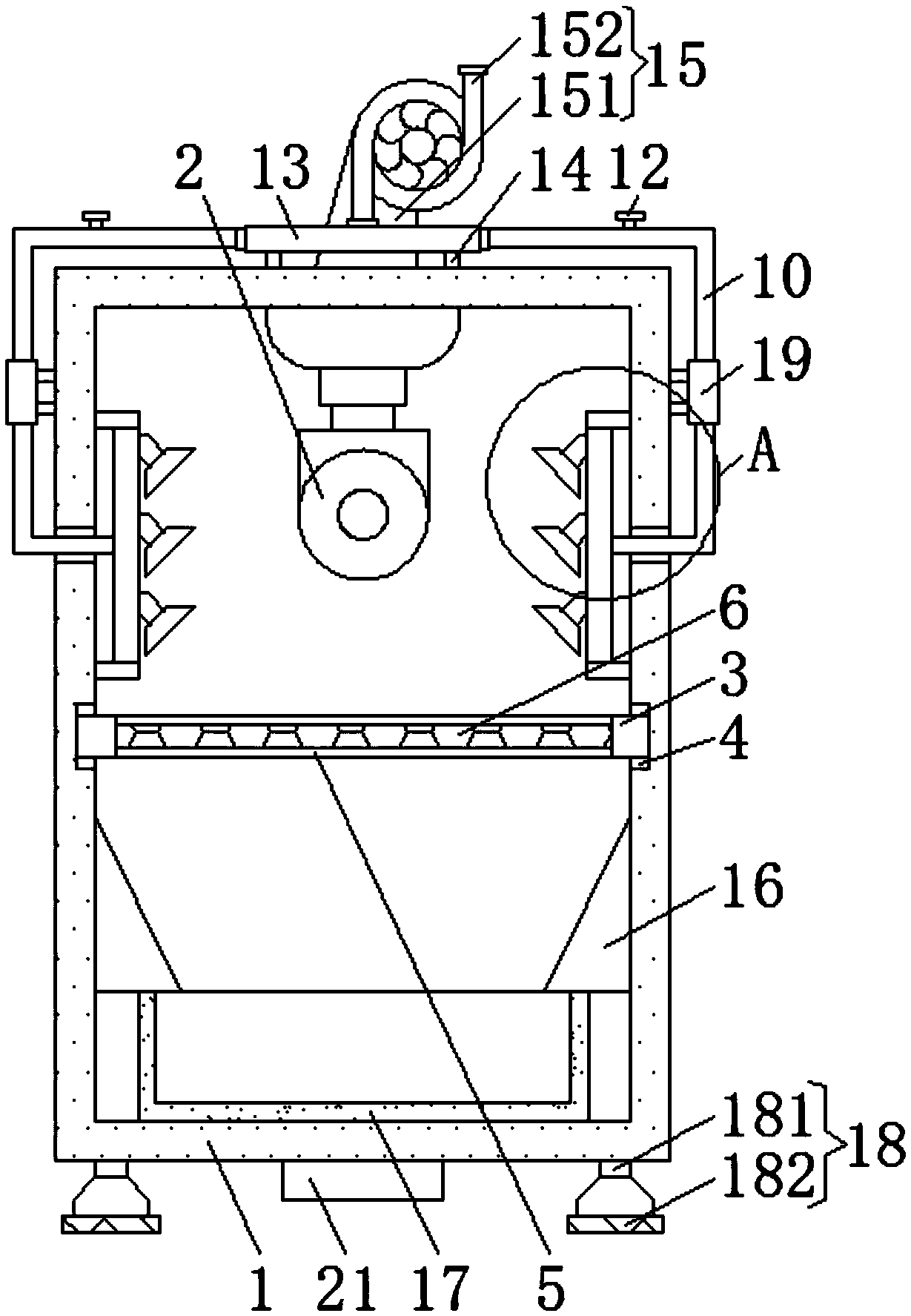
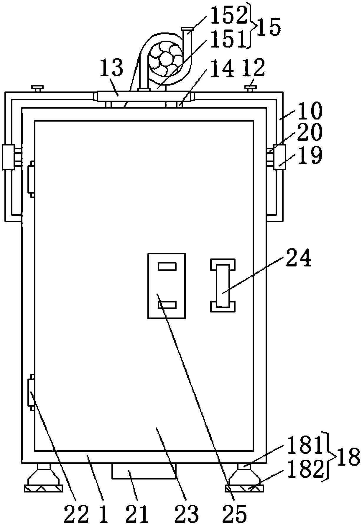
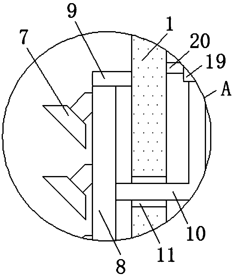
[0023] Such as Figure 1-3 As shown, the present invention provides a technical solution: a cutting machine tool for metal component processing, including a casing 1, a cutting machine 2 is arranged on the upper surface of the inner wall of the casing 1, and the left side of the front of the casing 1 passes through two hinges. 22 is hinged with the left side of the cover plate 23, the back side of the cover plate 23 is overlapped with the front of the housing ...


PUM


Abstract

The invention discloses a cutting machine tool for metal component machining. The cutting machine tool for metal component machining comprises a shell, wherein a cutting machine is arranged on the upper surface of the inner wall of the shell; an operating table is arranged below the cutting machine; the left and right side faces of the operating table are slidably connected to chutes formed in theleft and right side faces of the inner wall of the shell separately; a limiting hole is formed in the upper surface of the operating table; a filter plate is arranged in the limiting hole; and a storage box is arranged below the operating table, and the lower surface of the storage box is in overlapping joint to the lower surface of the inner wall of the shell. According to the cutting machine tool for metal component machining, sweeps are finally ejected through a nozzle and are acted to a metal component placed on the operating table, so that the sweeps generated on the surface of the metalcomponent flow out through a filter plate and are scattered in the storage box. Therefore, the sweeps on the surface of the metal component can be still processed immediately when the cutting machineis in the working state, so that the work efficiency of an operator can be improved, and the processing quality of the cutting machine can be also guaranteed.

Description

technical field [0001] The invention relates to the technical field of metal cutting machine tools, in particular to a cutting machine tool for processing metal components. Background technique [0002] Cutting machine tools are machine tools used for cutting, grinding or special processing methods to process various metal workpieces to obtain the required geometric shape, dimensional accuracy and surface quality. [0003] A large amount of metal waste will be generated during the processing of metal components by cutting machines. If these wastes are not cleaned up in time, they will act on the metal components with the action of the cutting machine, which will affect the smoothness of the surface of the components. However Most of the existing cleaning methods are that the operator cleans when the cutting machine is stopped, and the synchronous action cannot be achieved, which will not only affect the processing quality of the component surface, but also reduce the work ef...

Claims


Application Information

Patent Timeline
IPC IPC(8): B23D79/00B23Q11/00
CPCB23D79/00B23Q11/005
Inventor 陈发军
Owner 陈发军
Learn More