
Robot inner temperature adjusting system

A technology for internal temperature and regulation systems, applied in manipulators, manufacturing tools, etc., can solve problems such as difficult pump layout and pump failure, and achieve the effects of increasing temperature, ensuring stability, and simple temperature system

Pending Publication Date: 2018-11-06
EFORT INTELLIGENT EQUIP CO LTD
View PDF2 Cites 0 Cited by
  • Summary
  • Abstract
  • Description
  • Claims
  • Application Information

AI Technical Summary

Problems solved by technology

However, for industrial robots, due to their compact internal structure, it is difficult to arrange the pump. In addition, because the robot is under positive pressure, when the internal pressure of the robot is higher than the pressure of the pump supply gas, the pump will fail to work.

Method used


Image

  • Robot inner temperature adjusting system
  • Robot inner temperature adjusting system
  • Robot inner temperature adjusting system

Examples


Embodiment Construction

[0030] In order to make the technical means, creative features, goals and effects achieved by the present invention easy to understand, the present invention will be further elaborated below.

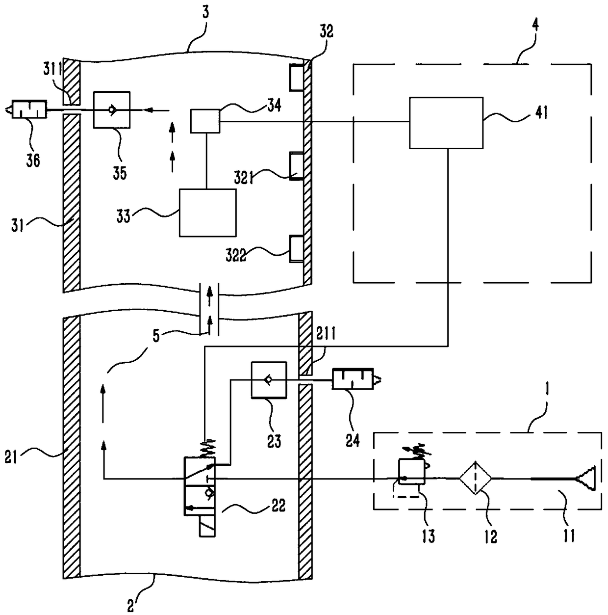
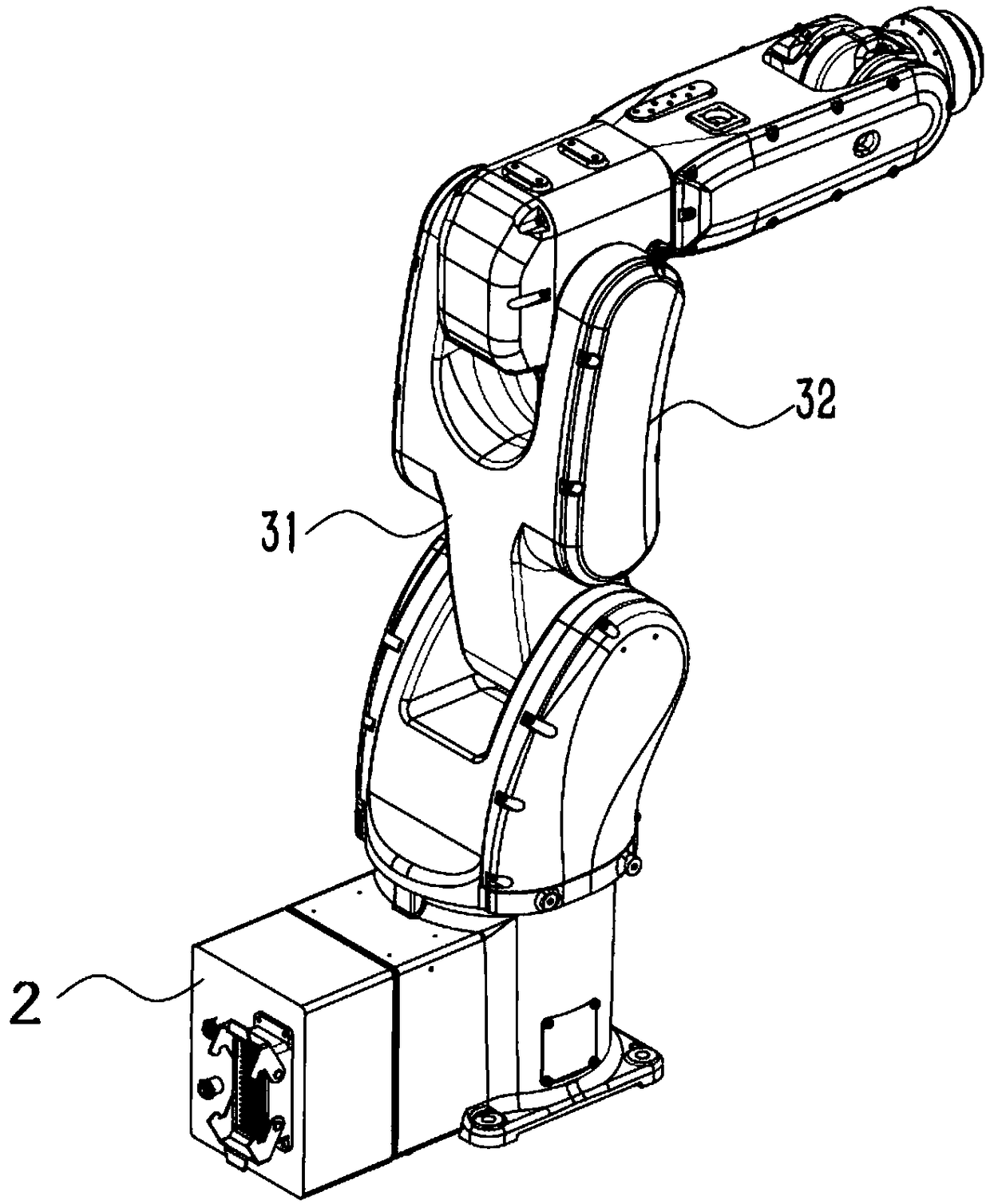
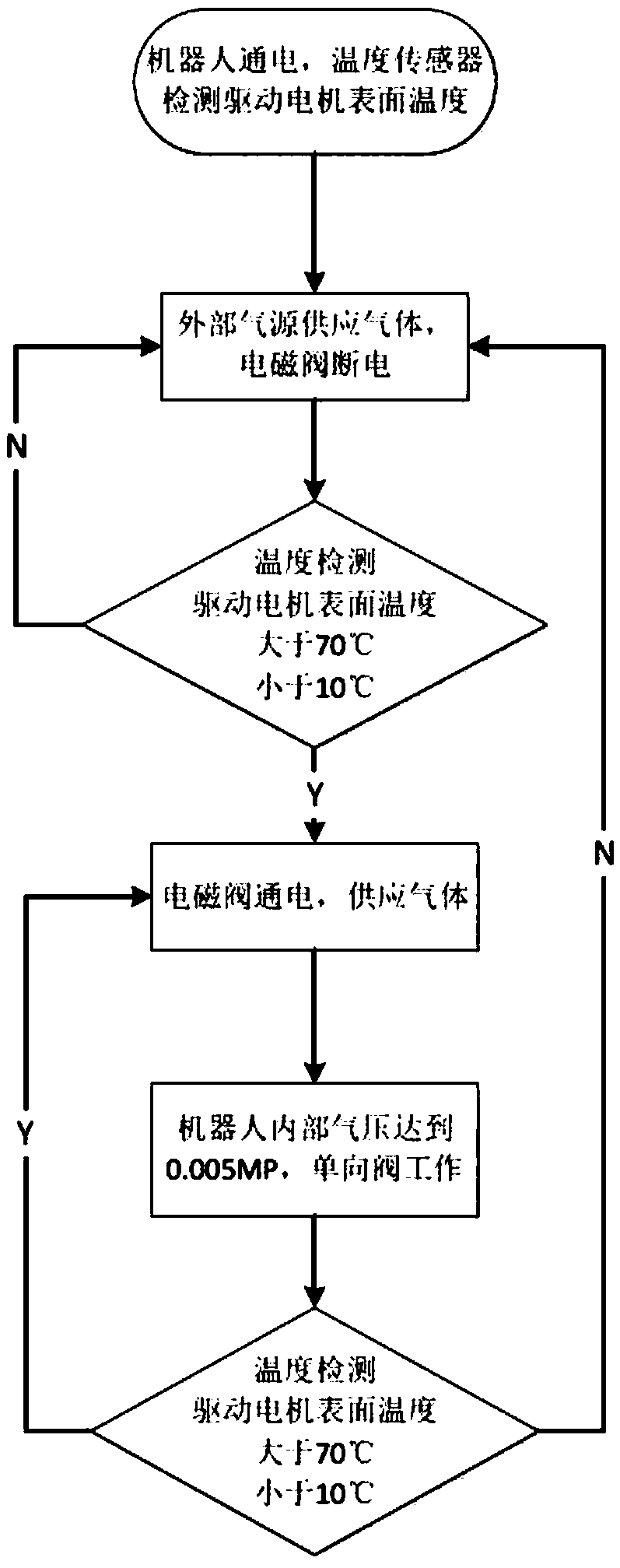
[0031] Such as Figure 1 to Figure 3 As shown, a robot internal temperature regulation system, including:

[0032] The first cavity 2 is located in the bottom of the robot;

[0033] The second cavity 3 is located at the arm of the robot and communicates with the first cavity 2;

[0034] The control system 4 receives the feedback signal in the second cavity 3 and outputs the signal to the first cavity 2;

[0035] The main gas circuit 1 supplies gas 5 to the first cavity 2 and the second cavity 3 which are both in a sealed state for heat exchange.

[0036] The first cavity 2 includes a base protection box 21, a solenoid valve 22 installed in the base protection box 21 and connected to the control system 4, a single valve installed on any side of the base protection box 21 and connected...


PUM


Abstract

The invention relates to a robot inner temperature adjusting system. The robot inner temperature adjusting system comprises a first cavity, a second cavity, a control system and a main gas circuit; the first cavity is located at the bottom of a robot; the second cavity is located on an arm of the robot and communicates with the first cavity; the control system is used for receiving feedback signals in the second cavity and transmitting the signals into the first cavity; and the main gas circuit is used for supplying gas to the first cavity and the second cavity which are both in a sealing state for heat exchange. According to the robot inner temperature adjusting system, the inner temperature of the robot can be quickly decreased or increased through heat exchange in the robot, the stability of the robot is guaranteed, noise generated in the exhausting process can be reduced, the condition that outside purities enter the robot can be avoided, and the working safety of the robot is guaranteed.

Description

technical field [0001] The invention relates to the technical field of industrial robots, in particular to a robot internal temperature adjustment system. Background technique [0002] At present, industrial robots are often used in harsh working environments, such as grasping on glass product production lines. The ambient temperature on site reaches 50°C. Due to the high sealing level of the robot itself, the heat inside the robot cannot be dissipated. When the internal temperature of the robot rises excessively, the high temperature will affect the electronic components inside the robot, resulting in reduced driving characteristics, fluctuations, etc., and even causing problems such as alarms and shutdowns of the robot; or used in working conditions where the ambient temperature is extremely low, Before the robot is working, its interior will be at a low temperature. The low temperature will cause the drive motor to fail to carry the load, or the speed of dragging the load...

Claims


Application Information

Patent Timeline
Patent Type & Authority Applications(China)
IPC IPC(8): B25J19/00
CPCB25J19/00B25J19/0054
Inventor 刘凯章林开亚骏肖永强张帷陈启勇
Owner EFORT INTELLIGENT EQUIP CO LTD
Learn More