
Layered composite type elastic cushion block and preparation method thereof

A layered composite and elastic pad technology, which is applied in the field of rail transit, can solve the problem that the elastic pad cannot meet the operating conditions, and achieve the effect of preventing the rate of change from being too large

Pending Publication Date: 2018-11-06
SICHUAN RUITIE TECH +1
View PDF6 Cites 0 Cited by
  • Summary
  • Abstract
  • Description
  • Claims
  • Application Information

AI Technical Summary

Problems solved by technology

Obviously, the traditional elastic cushion can no longer meet the requirements of the operating conditions

Method used


Image

  • Layered composite type elastic cushion block and preparation method thereof
  • Layered composite type elastic cushion block and preparation method thereof
  • Layered composite type elastic cushion block and preparation method thereof

Examples


Embodiment 1

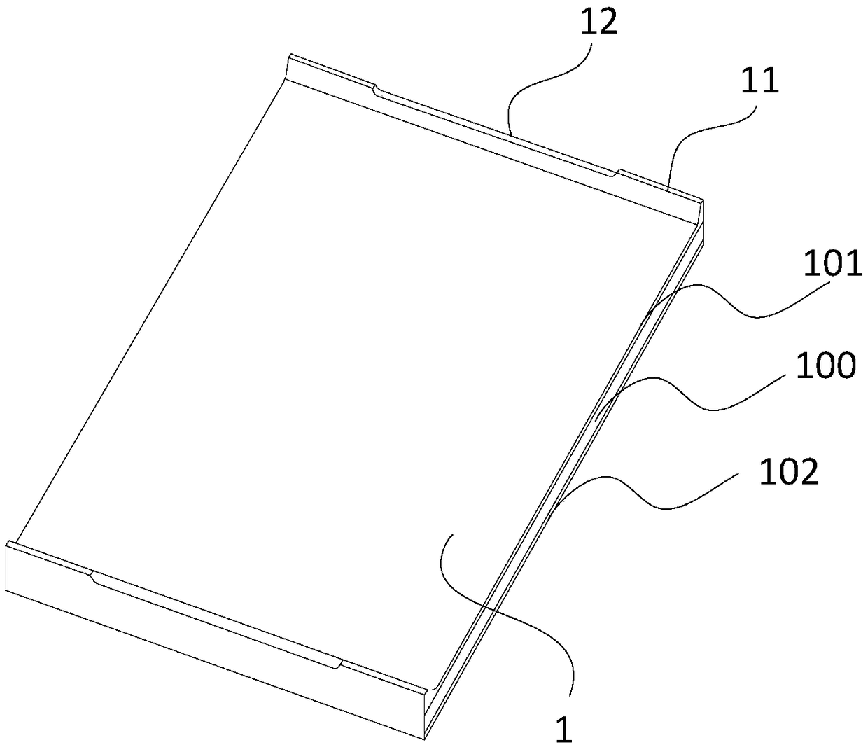
[0040] Such as Figure 2 to Figure 4 As shown, this embodiment provides a layered composite elastic pad, which aims to ensure the rigidity support, reduce the rate of static stiffness change, and at the same time ensure the shock absorption and buffering effects of the pad. Specifically, the composite elastic pad 1 includes an intermediate cushion layer 100 with a cuboid structure installed between the rigid rail and the concrete pillow, attached to the intermediate cushion layer 100, and used for the intermediate cushion layer 100 The lower thermal insulation layer 102 and the upper thermal insulation layer 101 for thermal insulation are arranged on the edges of both sides of the upper thermal insulation layer 101 and the side convex strips 11 integrally formed with the upper thermal insulation layer 101 are provided in any The concave strip 12 on the side convex strip 11 and the joint surface 13 provided between the side convex strip 11 and the upper thermal insulation layer...

Embodiment 2

[0042] Such as Figure 5 As shown, this embodiment provides a method for preparing a layered composite elastic cushion block, wherein the intermediate cushion layer is made of polyurethane, thermosetting elastomer material or rubber material. The material of the lower thermal insulation layer is the same as that of the upper thermal insulation layer, and is one of foamed silica gel and foamed rubber added with XPS polystyrene foam. The upper thermal insulation layer, the middle cushion layer and the lower thermal insulation layer are bonded sequentially from top to bottom.

[0043] Described preparation method comprises the following steps:

[0044] In the first step, put the white gray black in a vacuum oven and dry it under vacuum at 120°C for 3 hours to remove the moisture in the white gray black to obtain dry white gray black.

[0045] The second step, pretreatment of aluminum silicate fiber: first soak the fiber with 0.01mol / L hydrochloric acid solution and clean it wit...


PUM

PropertyMeasurementUnit
Thicknessaaaaaaaaaa
Thicknessaaaaaaaaaa
Thicknessaaaaaaaaaa

Abstract

The invention discloses a layered composite type elastic cushion block. The layered composite type elastic cushion block comprises a middle cushion layer which is installed between a steel rail and aconcrete sleeper and is of a rectangular solid structure, a lower heat preservation and insulation layer and an upper heat preservation and insulation layer which are arranged on the middle cushion layer and used for heat preservation and insulation of the middle cushion layer, side protruding strips arranged on the edges on the two sides of the upper heat preservation and insulation layer and integrally formed with the upper heat preservation and insulation layer, a concave strip formed in any side protrusion strip, and jointing faces arranged between the side protrusion strips and the upperheat preservation and insulation layer. The invention further discloses a preparation method of the layered composite type elastic cushion block. Through the above scheme, the layered composite type elastic cushion block has the beneficial effects of being simple in structure, long in service life, sufficient in rigid supporting strength and the like and has quite high practical value and popularization value in the technical field of rail traffic.

Description

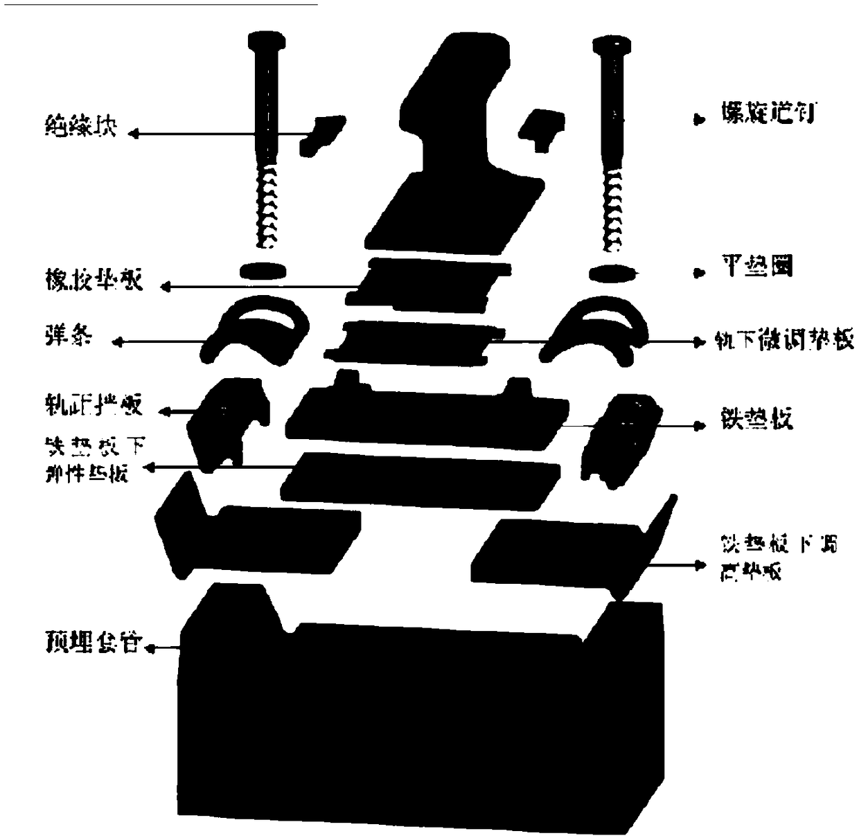
technical field [0001] The invention relates to the technical field of rail transit, in particular to a layered composite elastic pad and a preparation method thereof. Background technique [0002] The elastic pad is an important part of the heavy-duty line fastener system, which is installed under the rail (such as figure 1 shown), the elastic cushion can be divided into an upper elastic cushion and a lower elastic cushion with the iron backing plate as the boundary. Its main function is to buffer the high-speed impact and vibration generated when the vehicle passes the rail, protect the roadbed and sleepers, and protect the railway signal The system is electrically insulated. Not only that, the elastic cushion can also reduce the sinking of the track, maintain a high smoothness of the track, and reduce the workload of track maintenance and repair. [0003] The materials of the elastic cushion of the heavy-duty fastener system used at home and abroad mainly include rubber...

Claims


Application Information

Patent Timeline
IPC IPC(8): E01B9/68B32B3/30B32B27/40B32B27/06B32B25/04
CPCE01B9/683B32B3/30B32B25/04B32B27/06B32B27/40B32B2307/304B32B2307/50
Inventor 江万红巫江姚力卢野庞玲刘大园徐锡江曾榜荣蔡宏邓存宥翟淼杜华杨王根平董远孙超杰胡吉徐望
Owner SICHUAN RUITIE TECH
Learn More