Wire-passing structure for small flow rate center flow-concentrating flowmeter of oil field

A technology of small flow rate and flow meter, which is applied in the direction of measurement, drilling equipment, wellbore/well components, etc., can solve the problems caused by sealing plugs and rubber sleeves, require more key control points, and reduce reliability, etc., to achieve good protection Function, convenient and fast disassembly and assembly, and the effect of reducing pressure

Active Publication Date: 2018-11-06
四川省科学城久利电子有限责任公司
View PDF8 Cites 4 Cited by
  • Summary
  • Abstract
  • Description
  • Claims
  • Application Information

AI Technical Summary

Problems solved by technology

With the different use requirements of the flowmeter, the access of the collecting umbrella or circuit section or other ends to be installed at the upper and lower ends of the central collecting flowmeter requires that the central collecting flowmeter not only be able to measure the flow rate but also be able to pass through. The more common method is to use the soft wire welding sealing plug to match the sealing rubber sleeve to plug in the water channel of the central collector flowmeter, so the soft wire can only be directly connected in the flow channel, so there are serious problems : Both the flexible wire and the joint are soaked in the water hole filled with high-pressure liquid and connected with the oil pipe. When the sealing plug and the matching sealing rubber sleeve exceed 50MPa, the reliability of the sealing plug and the matching sealing rubber sleeve is reduced, and short circuit is easy to occur; the flexible wire plus the sealing plug and The sealing rubber sleeve requires that two more secondary lines must be connected, because the isolation of the high and low voltage areas must be maintained, which has caused another problem, that is, too many combinations of sealing plugs and rubber sleeves are easy to cause lesions, and there may be more There are many water leakage points, and there are many key control points

Method used


Image

  • Wire-passing structure for small flow rate center flow-concentrating flowmeter of oil field

Examples


Embodiment 1

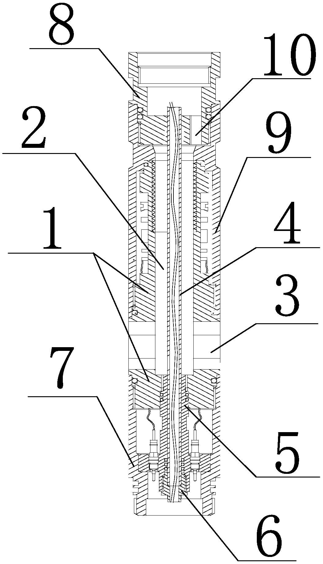
[0022] Such as figure 1 As shown, the present invention is a small-flow center-collecting flowmeter line-passing structure for oilfields, including a main body 1 for installing an electromagnetic flowmeter. The main body 1 is provided with a water-passing hole 2 that runs through the upper and lower end faces, and is close to the water-passing hole 2. The side wall of the main body 1 at the lower end of the hole 2 is provided with a water outlet 3 communicating with the water hole. The water hole 2 is provided with a wire passing steel pipe 4 for threading through the upper and lower ends of the water hole 2. The wire passing steel pipe 4 An annular liquid flow channel is formed between the outer wall of the water hole 2 and the inner wall of the water hole 2. The liquid flow channel communicates with the oil pipe through the top of the water hole 2 and the water outlet 3 to form a high-pressure zone. The outer walls of the upper and lower ends of the steel pipe 4 are sealed T...

Embodiment 2

[0025] The present invention is a line-passing structure for small-flow center-collecting flowmeters used in oil fields. On the basis of Embodiment 1, a steel pipe core 5 is sleeved between the inner wall of the lower end of the water passage hole and the outer wall of the steel pipe passing through the line. The inner wall and the outer wall of the core body are equipped with sealed O-shaped packing, and the inner wall of the steel pipe core body and the outer wall of the passing steel pipe are sealed by the sealed O-shaped packing, and the outer wall of the steel pipe core body and the lower end of the water hole on the main body The inner wall is sealed by sealing O-shaped packing; the lower end of the steel pipe core extends out of the water hole of the main body, and the inner wall of the lower end of the steel pipe core is provided with threads, and the inner wall of the lower end of the steel pipe core is threaded with a steel pipe positioning pressure core 6. The thread...

Embodiment 3

[0028] The present invention is a line-passing structure for a small-flow center-collecting flowmeter in an oil field. On the basis of Embodiment 1, the upper end of the main body is connected with a terminal 8, and a threading hole is provided in the terminal. The outer walls of the line steel pipes are sealed and connected by a sealed O-shaped packing, and a plurality of water inlet holes 10 are arranged around the wire hole, and the water inlet holes communicate with the annular liquid flow channel.

[0029] The upper end of the steel pipe passing through the line is sealed and connected to the inner wall of the upper end of the water hole through the end and the sealed O-shaped packing. There are multiple water inlet holes around the threading hole, that is, the liquid flow at the upper end enters through the water inlet holes. In the liquid flow channel, this can not only ensure that the upper liquid flow flows into the flowmeter for measurement, but also ensure the thread...


PUM


Abstract

The invention discloses a wire-passing structure for a small flow rate center flow-concentrating flowmeter of an oil field. The wire-passing structure comprises a main body for installing an electromagnetic flowmeter, and the main body is internally provided with a water passing hole penetrating the upper and lower end faces. A water outlet communicating with the water passing hole is formed in the side wall, close to the lower end of the water passing hole, of the main body, and a wire-passing steel pipe penetrating through the upper and lower ends of the water passing hole and used for threading is arranged in the water passing hole in a sleeved mode. An annular liquid flow passage is formed between the outer wall of the wire-passing steel pipe and the inner wall of the water passing hole. The outer walls of the upper and lower ends of the wire-passing steel pipe are separated from the liquid flow passage through a sealing structure. According to the wire-passing structure for the flowmeter, the wire-passing steel pipe is adopted to pass through a high-pressure zone in the water passing hole, and then an electric wire passes through the wire-passing steel pipe to divide the outerand inner space of the wire-passing steel pipe into high and low pressure zones, so that it is realized that the space is divided and a wire-passing passage is stable and strong, and the wire is notdirectly subjected to pressure bearing. The wire-passing steel pipe is installed once, the electric wire can be threaded for multiple times without damage, and the wire-passing structure is easy to disassemble and assemble and convenient to maintain.

Description

technical field [0001] The invention relates to a line-passing structure, in particular to a line-passing structure for a small-flow center-collection flowmeter in an oil field. Background technique [0002] The collecting flowmeter is that the liquid flow from the oil pipe through the collecting umbrella or through the water inlet flows through the central water hole of the collecting flowmeter during water injection, and then the electromagnetic flowmeter measures the flow through the central water hole. Liquid flow rate, calculated flow rate. With the different use requirements of the flowmeter, the access of the collecting umbrella or circuit section or other ends to be installed at the upper and lower ends of the central collecting flowmeter requires that the central collecting flowmeter not only be able to measure the flow rate but also be able to pass through. The more common method is to use the soft wire welding sealing plug to match the sealing rubber sleeve to pl...

Claims


Application Information

Patent Timeline
Patent Type & Authority Applications(China)
IPC IPC(8): E21B47/00E21B17/02
CPCE21B17/023E21B47/00
Inventor 陈军刘黄莹赵晓鹏赵海云涂高鹏夏涛同凯李小林
Owner 四川省科学城久利电子有限责任公司
Why Eureka
Try Eureka