Eureka AIR delivers breakthrough ideas for toughest innovation challenges, trusted by R&D personnel around the world.

Novel single-blade wheel type power generation device for electricity company

A technology of power generation device and electric industry, applied in the direction of reaction engine, hydroelectric power generation, engine components, etc., can solve the problems of single structure and strong operation applicability, and achieve the effect of increasing production cost, reducing service life and reducing power generation efficiency.

Inactive Publication Date: 2018-11-06
TAIZHOU DINGTUO IND DESIGN CO LTD
View PDF5 Cites 2 Cited by
  • Summary
  • Abstract
  • Description
  • Claims
  • Application Information

AI Technical Summary

Problems solved by technology

[0002] Electric energy is one of the most important energy sources in modern society. A generator is a mechanical device that converts other forms of energy into electrical energy. It was first produced during the Second Industrial Revolution and was made by German engineer Siemens in 1866. It consists of water turbines and steam turbines. , diesel engine or other power mechanical drive, the energy generated by water flow, air flow, fuel combustion or nuclear fission is converted into mechanical energy and transmitted to the generator, and then converted into electrical energy by the generator. The generator is used in industrial and agricultural production, national defense, science and technology and daily life There are a wide range of uses in the existing power equipment, including power generation through water turbines, and wind turbines, using wind energy or water energy to convert useful mechanical energy, and converting mechanical energy into electrical energy. place, energy saving, environmental protection and pollution-free, should be vigorously advocated and promoted, but most of the water turbine wind turbine power generation equipment has a single structure and strong operational applicability in the existing technology. For example, the invention patent with application number 201220654420.8 includes A generator wheel and a generator, the generator wheel is connected to the generator in transmission, the generator wheel includes a first generator wheel and a second generator wheel, the diameter of the first generator wheel is greater than the diameter of the second generator wheel, and the first generator wheel There are at least 4 blade groups interlaced with the second generator wheel, the first generator wheel and the second generator wheel are coaxially arranged on a transmission shaft, the transmission shaft is connected with the generator, and the blades The group includes at least two single blades that can be combined in a detachable manner. The generator wheel is a water wheel or a wind wheel. A reduction device is provided inside the generator, and the single blade is an arc blade. Although the structure of the invention is simple, But there are many deficiencies and defects. In the existing equipment, there are defects in the design of the first generator wheel and the second generator wheel. The connection between the first generator wheel and the second generator wheel and the transmission shaft is unstable. Shaking and tremors are prone to occur between the generator wheel, the second generator wheel and the transmission shaft, which reduces the service life of the transmission shaft, increases the production cost of the enterprise, and reduces the power generation efficiency, and the first generator wheel, the second generator wheel and the transmission There is no fixing device between the shaft and the generator. When in use, the connection between the transmission shaft and the generator is unstable, which may easily cause the generator to be damaged by impact, resulting in waste of resources for the generator and the transmission shaft. In view of these situations, in order to avoid Above-mentioned technical problem, it is really necessary to provide a kind of novel power company to use the monolithic wheel type power generation device to overcome the said defect in the prior art

Method used


Image

  • Novel single-blade wheel type power generation device for electricity company
  • Novel single-blade wheel type power generation device for electricity company
  • Novel single-blade wheel type power generation device for electricity company

Examples


Embodiment Construction

[0020] The following will clearly and completely describe the technical solutions in the embodiments of the present invention with reference to the accompanying drawings in the embodiments of the present invention. Obviously, the described embodiments are only some of the embodiments of the present invention, not all of them. Based on the embodiments of the present invention, all other embodiments obtained by persons of ordinary skill in the art without making creative efforts belong to the protection scope of the present invention.

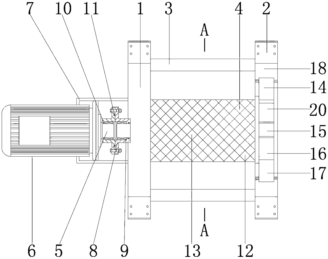
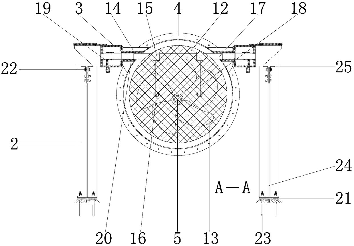
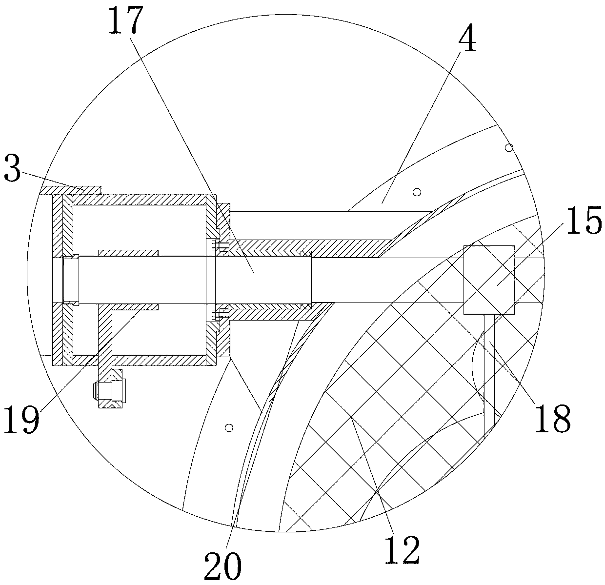
[0021] see Figure 1-4, the present invention provides a technical solution: a new single-chip wheeled power generation device for electric companies, including a bracket 1 for installing a generator 6 and a bracket 1, and the inner wall of the bracket 1 is equipped with a leg 2 for supporting Support 1, backing plate 21 is installed on the inner wall of supporting leg 2, is used to install hook-shaped reinforcing bar 23, and the outer wall of ba...


PUM


Abstract

The invention discloses a novel single-blade wheel type power generation device for an electricity company. The novel single-blade wheel type power generation device for the electricity company comprises a bracket, wherein supporting legs are mounted on the inner wall of the bracket; the outer walls of the supporting legs are connected to the inner walls of the bracket; pull rods are mounted between the inner walls of the bracket; the outer walls of the pull rods are connected to the inner walls of the bracket; a filter drum is mounted between the inner walls of the bracket; the outer wall ofthe filter drum is connected to the inner walls of the bracket; a rotary shaft is mounted on the inner wall of the filter drum; the outer wall of the rotary shaft is movably connected to the inner wall of the filter drum; and a rack is mounted on the outer wall of the left side of the bracket. According to the novel single-blade wheel type power generation device for the electricity company disclosed by the invention, by matching the bracket, the supporting legs and the rack, the product quality of the novel single-blade wheel type power generation device for the electricity company is improved, the procurement cost of a user is reduced, and waste of resources of the novel single-blade wheel type power generation device for the electricity company is avoided, and the novel single-blade wheel type power generation device for the electricity company is suitable for being popularized and used.

Description

technical field [0001] The invention relates to the technical field of water conservancy power generation, in particular to a novel single-chip wheel-type power generation device for electric companies. Background technique [0002] Electric energy is one of the most important energy sources in modern society. A generator is a mechanical device that converts other forms of energy into electrical energy. It was first produced during the Second Industrial Revolution and was made by German engineer Siemens in 1866. It consists of water turbines and steam turbines. , diesel engine or other power mechanical drive, the energy generated by water flow, air flow, fuel combustion or nuclear fission is converted into mechanical energy and transmitted to the generator, and then converted into electrical energy by the generator. The generator is used in industrial and agricultural production, national defense, science and technology and daily life There are a wide range of uses in the ex...

Claims


Application Information

Patent Timeline
Patent Type & Authority Applications(China)
IPC IPC(8): F03B13/00F03B3/12F03B11/00F03B11/08F03B11/04
CPCF03B3/121F03B11/00F03B11/04F03B11/08F03B13/00Y02E10/20
Inventor 周艳群
Owner TAIZHOU DINGTUO IND DESIGN CO LTD
Why Eureka
Eureka Blog
Learn More