Hydraulic cylinder self-locking mechanical mechanism for cleaning container and self-locking method of hydraulic cylinder self-locking mechanical mechanism

A technology of mechanical mechanism and hydraulic cylinder, applied in the field of self-locking equipment, can solve problems such as poor sealing, and achieve the effects of improving sealing, avoiding leakage and enhancing safety

Active Publication Date: 2018-11-06
ZHEJIANG JUHUA EQUIP MFG CO LTD
View PDF3 Cites 0 Cited by
  • Summary
  • Abstract
  • Description
  • Claims
  • Application Information

AI Technical Summary

Problems solved by technology

[0003] In view of the deficiencies in the prior art, the purpose of the present invention is to provide a hydraulic cylinder self-locking mechanica

Method used


Image

  • Hydraulic cylinder self-locking mechanical mechanism for cleaning container and self-locking method of hydraulic cylinder self-locking mechanical mechanism
  • Hydraulic cylinder self-locking mechanical mechanism for cleaning container and self-locking method of hydraulic cylinder self-locking mechanical mechanism

Examples


Embodiment 1

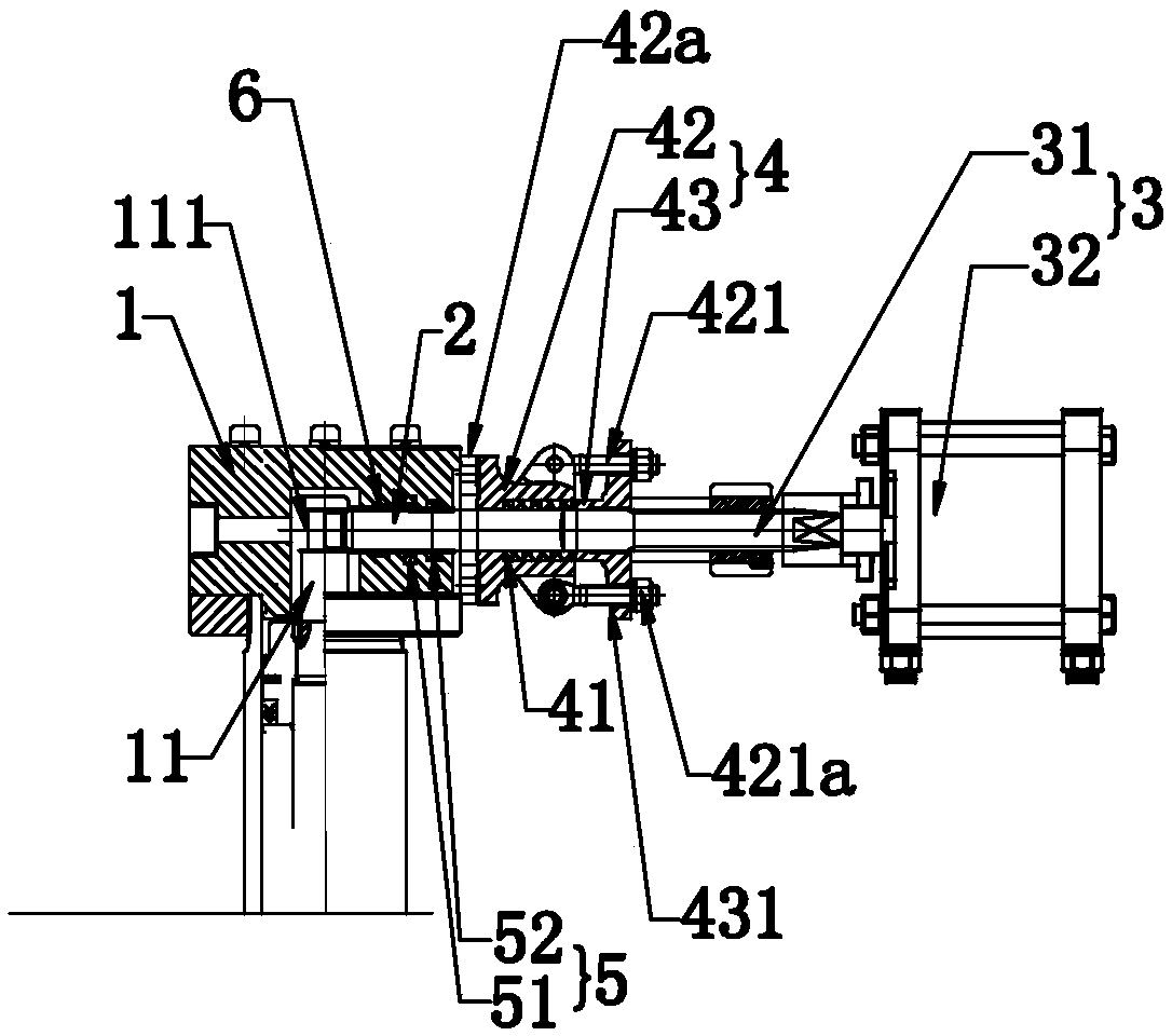
[0025] Such as figure 1 As shown, the present invention discloses a hydraulic cylinder self-locking mechanical mechanism for container cleaning, including a hydraulic cylinder block 1 and a piston 11 arranged inside the hydraulic cylinder block 1, and in a specific embodiment of the present invention, includes a hydraulic cylinder The latch groove 111 on 11, one end penetrates the inside of the hydraulic cylinder block 1 and can penetrate the self-locking pin 2 in the latch groove 111, the driving assembly 3 for driving the self-locking pin 2 to slide axially in the latch groove 111, and The closed packing mechanism 4 on the drive assembly 3 and the packing 41 located in the closed packing mechanism 4; when the closed packing mechanism 4 works, the packing 41 enters the gap between the self-locking pin 2 and the hydraulic cylinder block 1 The gap and / or the gap between the closed packing mechanism 4 and the drive assembly 3 completes the sealing of the hydraulic cylinder block...

Embodiment 2

[0039] Embodiment 2, the difference with embodiment 1 is

[0040] In a specific embodiment of the present invention, the valve stem 31 can be fixedly connected with the packing gland 43 .

[0041] By adopting the above technical scheme: when the cylinder controls the self-locking pin to enter the pin groove through the valve stem, the packing gland can be controlled synchronously to squeeze the packing, and when the self-locking pin completes the self-locking of the piston, the hydraulic cylinder can be completed in time. The sealing of the body, so as to further improve the sealing performance when self-locking, and further avoid leakage when the hydraulic cylinder is self-locking, and enhance the safety during use.

Embodiment 3

[0042] Embodiment 3, the difference with embodiment 1 is

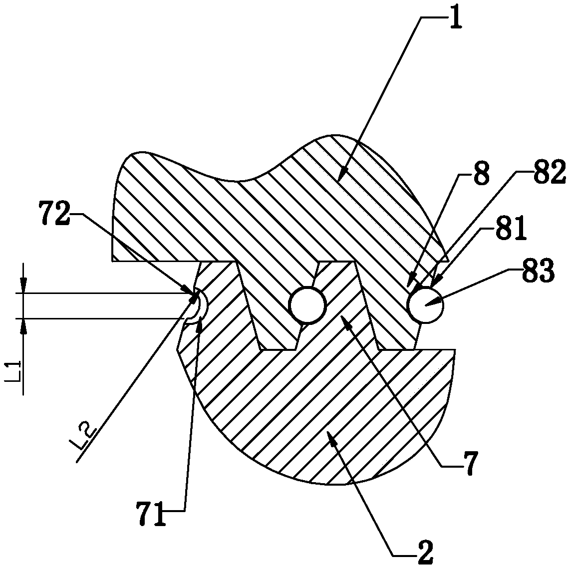
[0043] Such as figure 2 As shown, in a specific embodiment of the present invention, the outer wall of the self-locking pin 2 is provided with an external thread 7, and the contact surface between the hydraulic cylinder body 1 and the self-locking pin 2 is provided with a thread that is compatible with the external thread 7. The internal thread 8 of the internal thread 8 is provided with a plurality of first grooves 81 at intervals on the tooth wall of the thread of the internal thread 8, and the groove bottom of each first groove 81 is fixedly connected with the first groove through a compression element 82 The diameter of the ball 81 matches the ball 83, and the ball 83 is partially exposed outside the first groove 81. The thread of the external thread 7 is provided with a plurality of second grooves 71 that are compatible with each ball 83. The adjacent second grooves 71 communicate with each other through the mov...


PUM


Abstract

The invention relates to a hydraulic cylinder self-locking mechanical mechanism for cleaning a container and a self-locking method of the hydraulic cylinder self-locking mechanical mechanism. The hydraulic cylinder self-locking mechanical mechanism comprises a hydraulic cylinder body and a piston, wherein the piston is arranged inside the hydraulic cylinder body. The hydraulic cylinder self-locking mechanical mechanism is characterized in that the hydraulic cylinder self-locking mechanical mechanism comprises a plug pin groove, a self-locking pin, a driving assembly, a closed type filling mechanism and filler, wherein the plug pin groove is formed in the piston; one end of the self-locking pin penetrates into the hydraulic cylinder body and can penetrate into the plug pin groove; the driving assembly is used for driving the self-locking pin to slide in the plug pin groove in the axial direction; the closed type filling mechanism is arranged on the driving assembly; and the filler is arranged in the closed type filling mechanism. When the closed type filling mechanism works, the filler enters a gap formed between the self-locking pin and the hydraulic cylinder body and/or a gap formed between the closed type filling mechanism and the driving assembly, so that sealing of the hydraulic cylinder body is completed. The self-locking method of the hydraulic cylinder self-locking mechanical mechanism comprises the steps of 1, self-locking; 2, sealing; and 3, reset. The hydraulic cylinder self-locking mechanical mechanism and the self-locking method thereof have the beneficial effects that the structure is simple, sealing performance is great, and safety performance is high.

Description

technical field [0001] The invention relates to the technical field of self-locking equipment, in particular to a hydraulic cylinder self-locking mechanical mechanism for container cleaning and a self-locking method thereof. Background technique [0002] Reactor refers to a physical or chemical reaction container, which is mainly used in chemical industry and other industries; as a reaction container, it needs to be cleaned after long-term use to ensure the effect of the reaction As well as the quality of the reaction, in the prior art, the cleaning of the reactor is mainly to use the hydraulic cylinder to drive the actuator to clean the reactor; in the process of cleaning, the hydraulic cylinder needs to control the lock of the piston on the hydraulic cylinder through self-locking. The self-locking mechanism of the hydraulic cylinder mainly uses the cylinder to drive the pin to move, so that the pin moves axially and the pin is inserted into the pin groove in the upper cham...

Claims


Application Information

Patent Timeline
IPC IPC(8): F15B15/26B08B9/08
CPCF15B15/261B08B9/08F15B2015/267Y02W30/62
Inventor 吕治平陈汉涛施国有魏春华任占胜
Owner ZHEJIANG JUHUA EQUIP MFG CO LTD
Why Eureka
Try Eureka