Tension platform for synchronous-radiation light source CT (computed tomography) imaging

A technology of CT imaging and light source, which is applied in the direction of using wave/particle radiation for material analysis, using stable tension/pressure to test the strength of materials, and measuring devices, etc. It can solve the problems of in-situ real-time observation and research, and achieve high The effect of resolution

Active Publication Date: 2018-11-06
HARBIN INST OF TECH
View PDF9 Cites 5 Cited by
  • Summary
  • Abstract
  • Description
  • Claims
  • Application Information

AI Technical Summary

Problems solved by technology

[0004] The present invention aims to solve the problem that traditional analysis methods cannot realize in-situ real-time observation and research on the crack initiation and expansion process of structural materials under the action of external force. Observation and analysis of defects, complete in-situ observation of the fracture process on the synchrotron radiation CT imaging line station, there is no such device in the prior art, and it is necessary to provide a stretching table for synchrotron radiation light source CT imaging

Method used


Image

  • Tension platform for synchronous-radiation light source CT (computed tomography) imaging
  • Tension platform for synchronous-radiation light source CT (computed tomography) imaging

Examples


specific Embodiment approach 1

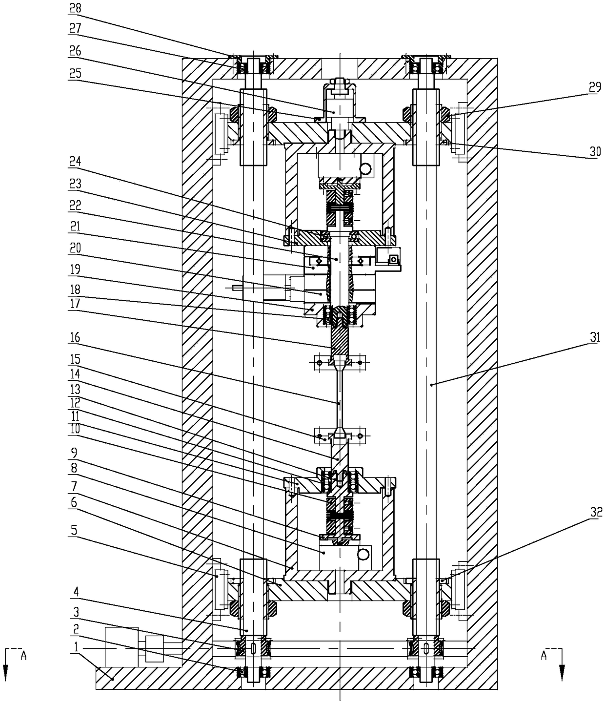
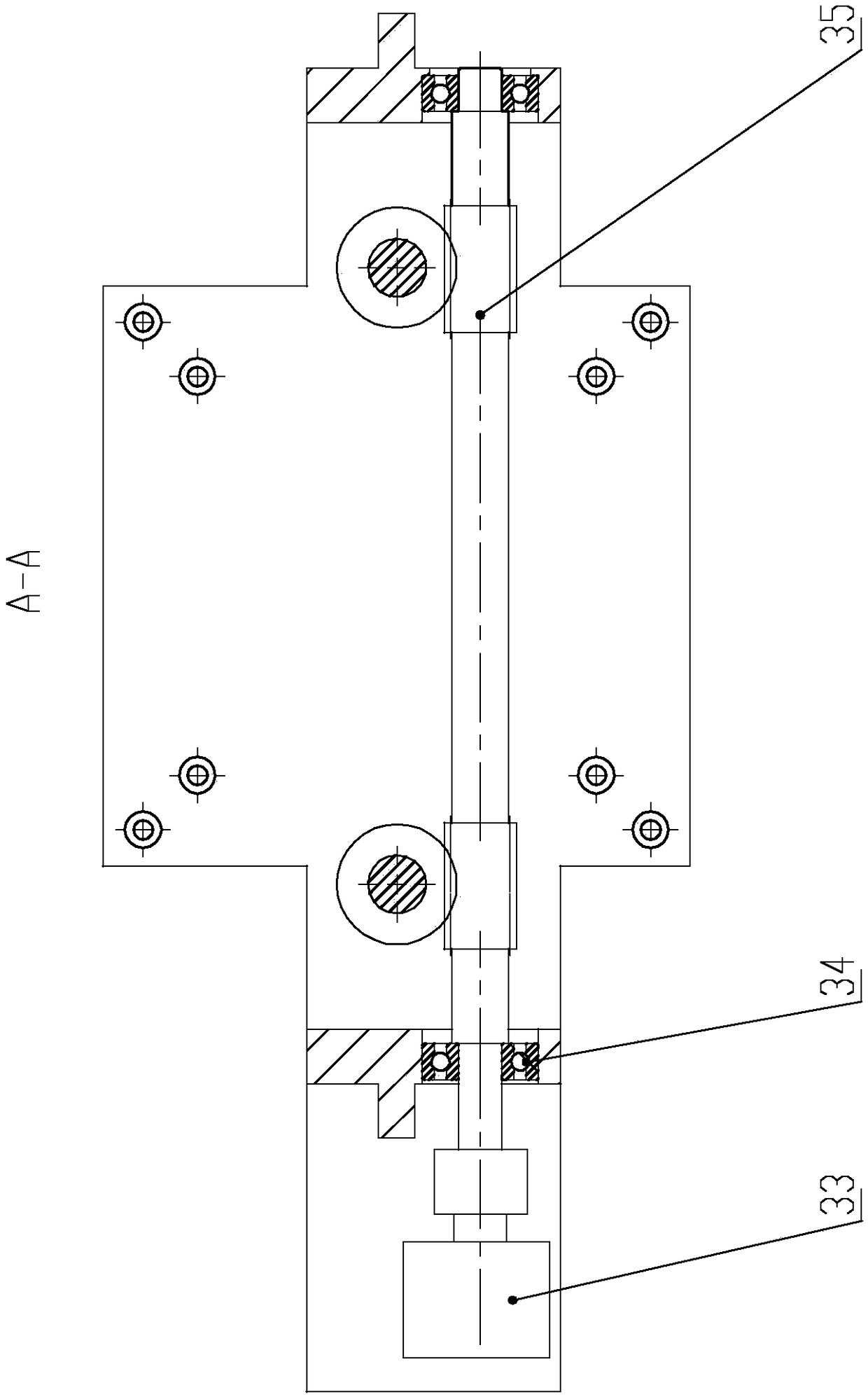
[0016] Specific implementation mode one: combine Figure 1-Figure 2 Describe this embodiment, the stretching table used for synchrotron radiation light source CT imaging described in this embodiment, it includes the stretching table frame base 1, the first positive and negative thread screw 4, the lower clamp bearing seat 11, the first The lower clamp shaft 13, the second lower clamp shaft 14, the second upper clamp shaft 17, the centering displacement mechanism connection block 19, the X displacement adjustment mechanism 20, the Y displacement adjustment mechanism 21, the upper clamp rotation shaft 22, the upper connection clamp 23, Force sensor 26, the second positive and negative lead screw 31, driving motor 33, worm screw 35, two worm gears 3, two slide block fixing plates 6, two connecting fixture concave frames 7, two with motor transmission mechanism Rotating body 8, two rotating body connecting shafts 9, two flexible couplings 10, two lead screw right-handed nuts 30, t...

specific Embodiment approach 2

[0019] Specific implementation mode two: combination figure 1Describe this embodiment, a stretching table for synchrotron radiation light source CT imaging described in this embodiment, it also includes two deep groove ball bearings 2 at the bottom of the screw, two deep groove ball bearings 27 at the top of the screw and two A deep groove ball bearing retaining ring 28, the bottom end of the first front and back screw 4 is equipped with a deep groove ball bearing 2 at the bottom of the screw, and the top of the first front and back screw 4 is equipped with a deep groove on the top of the screw The ball bearing 27, and the top of the first forward and reverse threaded screw 4 and the deep groove ball bearing 27 on the top of the leading screw are installed on the frame base 1 of the stretching table through the deep groove ball bearing retaining ring 28, and the second positive and negative threaded The bottom end of the leading screw 31 is fitted with a deep groove ball beari...

specific Embodiment approach 3

[0020] Specific implementation mode three: combination figure 1 Describe this embodiment, a stretching table for CT imaging of a synchrotron radiation light source described in this embodiment, it also includes a thrust ball bearing 24, two lower connecting angular contact bearings 12 and two upper connecting angular contact bearings 18, The two lower connecting angular contact bearings 12 are installed on the lower fixture bearing housing 11, the first lower fixture rotating shaft 13 is inserted into the two lower connecting angular contact bearings 12, and the two upper connecting angular contact bearings 18 are installed on the centering displacement mechanism to connect On the block 19, one end of the upper fixture rotating shaft 22 close to the second upper fixture rotating shaft 17 is inserted on the two upper connecting angular contact bearings 18, the thrust ball bearing 24 is installed on the upper connecting fixture 23, and the upper fixture rotating shaft 22 is close...


PUM


Abstract

The invention provides a tension platform for synchronous-radiation light source CT (computed tomography) imaging, and relates to a tension platform. The tension platform aims at solving the problem of failure to observe and study the crack generation and expansion process of the structural material under the function of external force by the traditional analysis method in situ and in real time; by adopting the synchronous-radiation X-ray CT imaging, the internal defect of a millimeter-level specimen can be observed and analyzed by using high penetration ability; the cracking process can be observed in situ on the synchronous-radiation CT imaging line station; the tension platform is not available in the prior art. The tension platform comprises a first positive and reverse screw rod, a lower clamp bearing block, an X-axis displacement adjusting mechanism, a Y-axis displacement adjusting mechanism, an upper clamp rotary shaft, an upper connecting clamp, a force sensor, a second positive and reverse screw rod, a drive motor, a worm, two worm wheels, two sliding block fixing plates, two rotary bodies with motor drive mechanisms, two rotary body connecting shafts, two flexible couplings, two clamps and four guide rail sliding blocks. The tension platform belongs to the field of tension of light source imaging.

Description

technical field [0001] The invention relates to a stretching table, in particular to a stretching table used for CT imaging of a synchrotron radiation light source. Background technique [0002] Synchrotron X-rays have become an important detection tool for modern science due to their advantages of high brightness, high energy, high coherence, and high collimation. Europe, America, Japan and my country have all built their own large scientific devices for synchrotron radiation. Among them, CT imaging is an important application of synchrotron radiation technology. This method can be used to realize non-destructive testing of the internal structure of samples such as materials, organisms, and minerals, and is widely used in research fields such as materials, biology, archaeology, and geology. [0003] The failure behavior of structural materials under external force has always been an important fundamental issue in the field of materials science, and its process can be divid...

Claims


Application Information

Patent Timeline
Patent Type & Authority Applications(China)
IPC IPC(8): G01N3/08G01N23/046
CPCG01N3/08G01N23/046
Inventor 唐光泽范国华王同敏康慧君郑德志
Owner HARBIN INST OF TECH
Why Eureka
Try Eureka