
Test machine cabinet

A cabinet, to-be-tested technology, applied in the direction of measuring electricity, measuring devices, measuring electrical variables, etc., can solve the problems of waste of economy and site utilization, prone to unstable contact, large occupied volume, etc., to improve aging efficiency, Improve test efficiency and simple operation

Pending Publication Date: 2018-11-06
WUHAN SOUTH SAGITTARIUS INTEGRATION CO LTD
View PDF0 Cites 0 Cited by
  • Summary
  • Abstract
  • Description
  • Claims
  • Application Information

AI Technical Summary

Problems solved by technology

[0002] At present, most of the testing of module products is to place the products to be tested on the test turnover car, and then connect each product to be tested one by one (including power signal and / or test signal), but this operation method is very inefficient, and prone to contact instability
Moreover, most of the existing modular test equipment is to realize the aging of a single product, and it is necessary to repurchase or manufacture test turnover vehicle equipment when replacing a product
And it occupies a large volume, which causes relatively large waste in terms of economy and site utilization

Method used


Image

  • Test machine cabinet
  • Test machine cabinet

Examples


Embodiment Construction

[0029] The principles and features of the present invention are described below in conjunction with the accompanying drawings, and the examples given are only used to explain the present invention, and are not intended to limit the scope of the present invention.

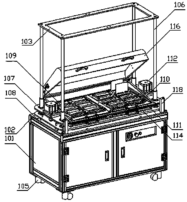
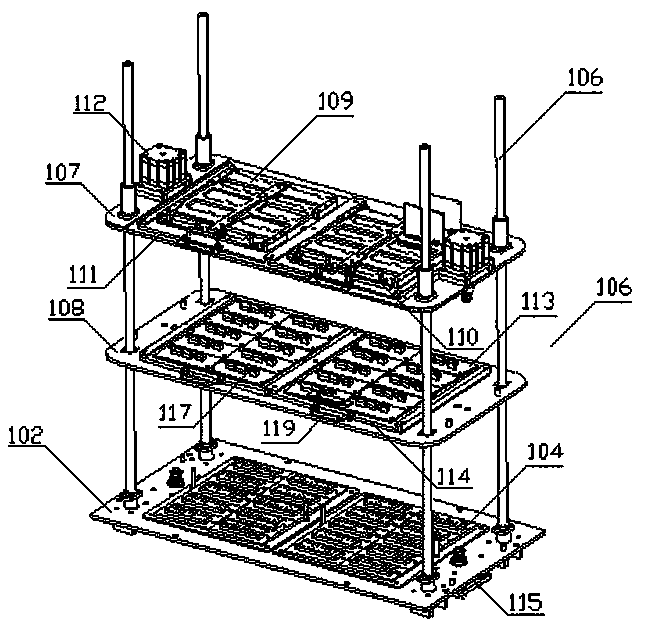
[0030] Such as figure 1 and figure 2As shown, a test cabinet includes a test box 101 with an open upper end, a fixed plate 102, a connecting plate, a heating shield 116 and a top plate 103, the fixed plate 102 is covered on the upper end of the test box 101, and the fixed plate 102 is provided with a thimble base plate 104 on the upper surface, the lower surface of the fixed plate 102 is provided with a first adapter plate, the four peripheral corners of the fixed plate 102 are respectively provided with guide rods 106, and the four peripheral corners of the connecting plate are respectively provided with guide rods 106. The corners are respectively sleeved in the middle of the corresponding guide rods 106, and mo...


PUM


Abstract

The invention relates to a test machine cabinet. The test machine cabinet comprises a test box, a fixed plate, a connecting plate, a heating protective cover and a top plate; the fixed plate is arranged at the upper end of the test box in a covering way; a thimble substrate is arranged on the upper surface of the fixed plate; a first adapter plate is arranged on the lower surface of the fixed plate; guide rods are arranged at the peripheral corners of the fixed plate correspondingly; the connecting plate is arranged at the middle part of each guide rod in a sleeving way and moves up and down along the guide rod; a plurality of to-be-tested modules are arranged on the connecting plate; the plurality of to-be-tested modules are arranged on the connecting plate at intervals; the thimble substrate is electrically connected with the first adapter plate; and the first adapter plate is electrically connected with an external host. According to the test machine cabinet, all the to-be-tested modules are electrically connected with the thimble substrate simultaneously and automatically when the connecting plate moves downwards to the very bottom, so that the test machine cabinet facilitatesbatched operation, is simple to operate and greatly improves the test efficiency; furthermore, after the test ends up, the connecting plate moves upwards, so that all the to-be-tested modules can be automatically disconnected.

Description

technical field [0001] The invention relates to the technical field of automatic detection, in particular to a testing cabinet. Background technique [0002] At present, most of the testing of module products is to place the products to be tested on the test turnover car, and then connect each product to be tested one by one (including power signal and / or test signal), but this operation method is very inefficient, and It is prone to contact instability. In addition, most of the existing modular test equipment is designed to realize the aging of a single product, and it is necessary to repurchase or manufacture test turnover vehicle equipment when replacing a product. And it takes up a large volume, which causes relatively large waste in terms of economy and site utilization. Contents of the invention [0003] The technical problem to be solved by the present invention is to provide a test cabinet for the above-mentioned deficiencies in the prior art. [0004] The techn...

Claims


Application Information

Patent Timeline
Patent Type & Authority Applications(China)
IPC IPC(8): G01R31/01
CPCG01R31/01
Inventor 叶聪陈星熊济方汪绍文石宏黄诗郁莹徽许锐黄思远
Owner WUHAN SOUTH SAGITTARIUS INTEGRATION CO LTD
Learn More