Supercharge Your Innovation With Domain-Expert AI Agents!

Toner cartridge of novel magnetic roller

A magnetic roller and toner cartridge technology, which is applied in the electric recording process applying charge pattern, the equipment of electric recording process applying electric charge pattern, electric recording technique, etc. Problems such as deformation of metal spacers, saving man-hours and reducing costs

Pending Publication Date: 2018-11-06
广州奥盛电子科技有限公司
View PDF1 Cites 0 Cited by
  • Summary
  • Abstract
  • Description
  • Claims
  • Application Information

AI Technical Summary

Problems solved by technology

At present, the sheath and the magnetic roller are separated. When assembling the toner cartridge, a sheath is installed at both ends of the magnetic roller, which is inconvenient to operate. Moreover, since the sheath and the magnetic roller are not sealed, during installation and printing, Foreign matter such as toner can easily enter between the sheath and the magnetic roller, which increases the distance between the photosensitive drum and the magnetic roller, resulting in reduced printing blackness
Application No. 201721519199.4 "A New Type of Toner Cartridge Magnetic Roller Improvement Structure" discloses a magnetic roller structure in which metal spacers are respectively fixed on the outer sides of the two ends of the aluminum sleeve. Although it can solve the problem of carbon powder entering the sheath, the structure There are two disadvantages: the first is that the precision requirements of the inner diameter of the metal spacer and the outer diameter of the aluminum sleeve are very high. If the accuracy of the metal spacer cannot meet the requirements, there will be defects in the printing blackness. The second is to ensure that Under the premise of precision, it is difficult to install the metal spacer on the aluminum tube, and it is prone to deformation of the aluminum tube and the metal spacer. The third is that the processing cost of the metal spacer is high under the high precision requirements. Not competitive in higher industrial production

Method used


Image

  • Toner cartridge of novel magnetic roller
  • Toner cartridge of novel magnetic roller
  • Toner cartridge of novel magnetic roller

Examples


Embodiment Construction

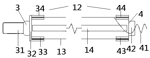
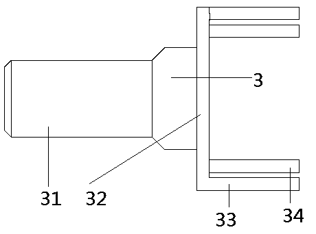
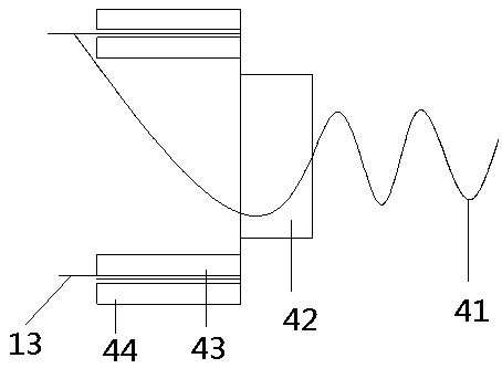
[0007] Below in conjunction with accompanying drawing, the present invention is described in detail: with reference to accompanying drawing figure 1 , attached figure 2 And attached image 3 , a novel magnetic roller toner cartridge, comprising a waste toner bin 2, a cleaning blade 23, a charging roller 22, a photosensitive drum 21, a powder scraper 17, a powder bin 1, a magnetic roller 12 and toner 18. The waste toner bin 2 is a part of the shell structure of the toner cartridge, on which a cleaning scraper 23, a charging roller 22 and a photosensitive drum 21 are installed; Roller 12 and toner 18; waste toner bin 2 and powder bin 1 form a toner cartridge. The magnetic roller includes a magnetic core 14 , a magnetic sleeve 13 , a rubber head 4 at a conductive end, and a rubber head 3 at a gear end. The magnetic core 14 is a cylindrical magnetic rod, the magnetic sleeve 13 is a circular aluminum tube coated with an adsorption layer, the magnetic core 14 is installed in the...


PUM


Abstract

The invention discloses a magnetic roller with a sheath. The magnetic roller comprises a waste powder cabin, a cleaning scraper, a charging roller, a photosensitive drum, a powder out scraper, a powder cabin, a magnetic roller and carbon powder. The magnetic roller comprises a magnetic core, a magnetic sheath, a conductive end glue head, and a gear end glue head; the magnetic core is arranged in the magnetic sheath, the gear end glue head is composed of a gear fixed column, a gear end fixed frame, a gear end connecting column and a gear end sheath glue layer; the conductive end glue head is composed of a conductive wire, a conducive end fixed frame, a conductive end connecting column and the conductive end sheath glue layer; two ends of the magnetic sheath are respectively inserted into the gaps between the connecting column of the gear end glue head and the sheath glue layer and between the connecting column of the conductive end glue head and the sheath glue layer and then hermetically fixed by using the glue; the thicknesses of the gear end sheath glue layer and the conductive end sheath glue layer are same, and the gear end sheath glue layer and the conductive end sheath glue layer can be manufactured as required thickness according to different models and configuration. The magnetic roller with the sheath has the advantages that the man hour is saved and the cost is reduced; and the printing abnormity caused by the carbon powder and like foreign matters entering the sheath can be avoided.

Description

technical field [0001] The invention discloses a novel magnetic roller toner cartridge, relates to the technical field of printers, in particular to a toner cartridge. Background technique [0002] At present, most of the toner cartridges for beating development in the market use magnetic rollers as an accessory for intermediate transfer. Since the main body of the magnetic roller is an aluminum tube with a rough coating on the surface, the photosensitive drum cannot be in direct contact with the magnetic roller. , It is necessary to use a sheath to separate the photosensitive drum and the magnetic roller at a certain distance. This distance is controlled by changing the thickness of the sheath. The larger the distance between the photosensitive drum and the magnetic roller, the lower the blackness of the printed sample. At present, the sheath and the magnetic roller are separated. When assembling the toner cartridge, a sheath is installed at both ends of the magnetic roller...

Claims


Application Information

Patent Timeline
IPC IPC(8): G03G15/08G03G15/09
CPCG03G15/0817G03G15/0942
Inventor 彭煦潘鹏
Owner 广州奥盛电子科技有限公司
Features
  • R&D
  • Intellectual Property
  • Life Sciences
  • Materials
  • Tech Scout
  • Unparalleled Data Quality
  • Higher Quality Content
  • 60% Fewer Hallucinations
Learn More